Do you have a question about the Yamaha B-I and is the answer not in the manual?
Details the revolutionary Yamaha Vertical Field Effect Transistor technology used in the B-I.
Explains the superior performance, linear transfer, and operational advantages of the vertical FET.
Presents detailed electrical and maximum rating characteristics for the 2SK77 and 2SK75 FETs.
Controls the signal level for speaker outputs when set to Normal input.
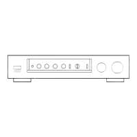
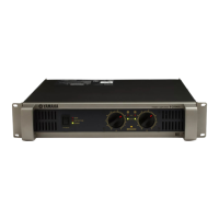
Explains the Power Switch and indicator lamps (Power, Thermal, Overload).
Five sets of terminals; set 1 active alone. Use 4-16 ohm speakers.
Connect to ground for hum problems; not needed for standard preamp connection.
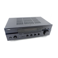
Connect preamplifier outputs; ensure firm insertion. Controls bypassed in Direct mode.
Filters low-frequency noise (turntable rumble). Active in Normal mode.
Remote control power terminal for use with a Yamaha C-I preamplifier.
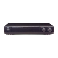
Controls power for UC-I and B-I; indicators function like B-I's.
Replaces B-I's filter switch. B-I rear switch must be off for UC-I switch to work.
Wide display range (-50dB to +5dB) for precise output indication.
Steps for physically connecting the UC-I to the B-I.
Factory-adjusted meters; consult service agent for adjustments.
Covers Speaker On/Off, Speaker Selectors, and Speaker Level Controls.
Steps for connecting B-I, UC-I, and RU-I using the remote control kit.
Explains how B-I controls are bypassed and UC-I operation when using RU-I.
Details the filter amplifier's construction, characteristics, and rumble filter.
Details the construction of the amplifier's primary, second, and final stages.
Explains features of the dual FET, cascode, and Darlington-connected circuits.
Describes separate power sources, thermal protectors, and automatic shutoff.
Details specifications of high-capacity electrolytic capacitors used in power stages.
Detects DC output and protects speakers, also cuts shock noise.
Protects against excessive current, shorts, and bias abnormalities.
Shuts off power if heat sinks rise above 100°C.
Illustrates the signal flow and component interconnections within the B-I amplifier.
Presents oscilloscope charts for distortion and element waveforms.
Shows frequency response and tone burst response characteristics.
Graphs showing output vs. distortion and impedance vs. output.
Graphs illustrating frequency response, phase, and power bandwidth.
Detailed technical specifications for the B-I amplifier.
Lists meter range, indication, dimensions, and weight for the UC-I.
Details the cord length and stand for the RU-I remote control kit.