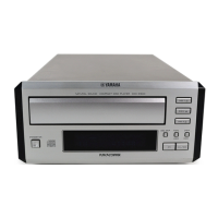
CDX-E400
CDX-E400
7
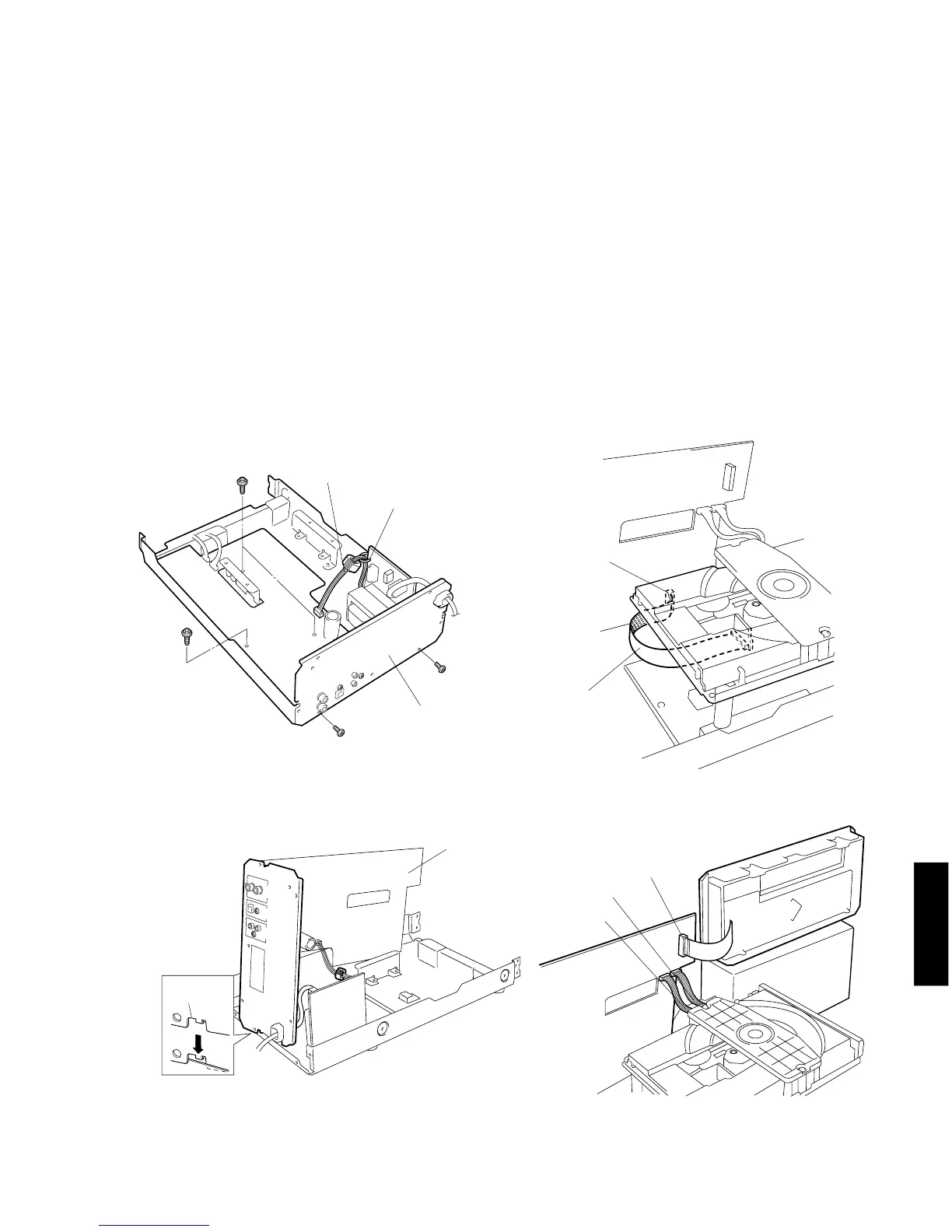
● Servicing Position
a. Remove the Top Cover, Front Panel and CD Mechanism Unit.
b. Remove 3 screws (y) and 2 screws (u) in Fig. 3.
c. Loosen the style pin (PN1) to set W401 free in Fig. 3.
d. With the rear panel attached, remove the Main P.C.B.
e. With the rear panel attached, set the Main P.C.B on its side as shown in Fig. 4.
At this time, fit the cut in the rear panel with the main chassis as shown in Fig. 4.
f. Replace the PU cable of the CD Mechanism with the below specified extension cable.
Extension cable
16P 230 mm: V3340500
g. Install the CD Mechanism to the frame mechanism.
h. Connect CB1 as shown in Fig. 5.
i. Connect W2 and W3 to the CD Mechanism as shown in Fig. 6.
j. Place the front panel on the base as shown in Fig. 6.
Base height: 10cm
k. Connect CB102 as shown in Fig. 6.
l. Connect the power cable, turn on the power and check for operation.
Fig. 3
Fig. 4
Cut
Main P.C.B.
y
Rear Panel
y
u
u
Style Pin (PN1)
W401
Main P.C.B.
Fig. 5
Fig. 6
CB1
Extension cable
W2
W3
CB102
Base