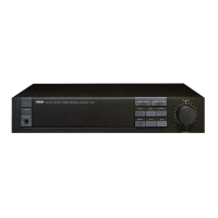
[250]
(Fig. 7)
[250]
Front panel
<Front View>
[250]: Oval Head Screw 4.0X8 MFZN2BL (VS153600)
8. Front Panel (time required: about 5 minutes)
8-1 Remove the top cover. (See procedure 1.)
8-2 Remove the six (6) screws marked [250]. The front panel
can then be removed. (Fig. 7)
9.
AC1/6, AC4/6, AC5/6 and AC6/6 Circuit Board
(time required: about 20 minutes)
9-1 Remove the top cover. (See procedure 1.)
9-2 Remove the front panel (See procedure 8.)
9-3 AC1/6 Circuit Board:
Pull out the power switch knob. (Fig. 6)
Remove the two (2) screws marked [60]. The AC1/6 circuit
board can then be removed. (Fig. 6)
9-4 AC4/6 Circuit Board:
Pull out the attenuation knobs. (Fig. 6)
Remove the two (2) hexagonal nuts marked [D]. The AC4/6
circuit board can then be removed. (Fig. 6)
9-5 AC5/6 Circuit Board:
Remove the screw marked [100A]. The AC5/6 circuit board
can then be removed. (Fig. 6)
9-6 AC6/6 Circuit Board:
Remove the screw marked [100B]. The AC6/6 circuit board
can then be removed. (Fig. 6)
• PA Unit
[80B]
[80B]
[80B]
[80B]
[80B]
[80B]
(Fig. 5)
Transistor holder (L)
Transistor holder (R)
[40]
PA
PA
[40]: Bind Head Screw SP 3.0X8 MFZN2BL (EG330290)
[80B]: Bind Head Tapping Screw-B 3.0X12 MFZN2BL (VQ074600)
(Fig. 6)
[50]: Bind Head Screw 4.0X8 MFZN2BL (EG340360)
[60]: Bind Head Screw 3.0X8 MFZN2BL (VB659000)
[100]: Bind Head Tapping Screw-B 3.0X8 MFZN2BL (EP600190)
[60] x 2
[D]
[50]
Fan
AC 1/6
AC 4/6
Power switch
knob
Attenuation knob
AC 5/6
AC 6/6
[100A]
[100B]
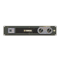
CP2000
10
6. PA Unit & PA Circuit Board
(time required: about 15 minutes)
6-1 Remove the top cover. (See procedure 1.)
6-2 Remove the six (6) screws marked [160]. The PA unit can
then be removed. (Fig. 2)
6-3 Remove the eighteen (18) screws marked [80B]. And then
remove the left and right transistor holders from the PA unit.
(Fig. 5)
6-4 Remove the six (6) screws marked [40]. And then remove
the PA circuit board from the PA unit. (Fig. 5)
7. DC Fan (time required: about 8 minutes)
7-1 Remove the top cover. (See procedure 1.)
7-2 Remove the PA unit. (See procedure 6-2.)
7-3 Remove the two (2) screws marked [50]. The fan can then
be removed. (Fig. 6)