EasyManua.ls Logo

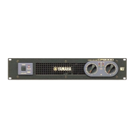
Yamaha CP2000 Service Manual

Yamaha CP2000
32 pages
To Next Page IconTo Next Page
Page #1 background imageLoading...
Page #1 background image
SERVICE MANUAL
PA
011553
HAMAMATSU, JAPAN
1.222K-496 Printed in Japan '00.11
CONTENTS
SPECIFICATIONS···································································· 3
PANEL LAYOUT······································································· 4
CIRCUIT BOARD LAYOUT ······················································ 5
WIRING····················································································· 6
DIMENTIONS ··········································································· 7
BLOCK DIAGRAM···································································· 8
DISASSEMBLY PROCEDURE················································· 9
IC BLOCK DIAGRAM ····························································· 11
CIRCUIT BOARDS ································································· 12
INSPECTIONS········································································ 17
PARTS LIST
OVERALL CIRCUIT DIAGRAM
POWER AMPLIFIER
This document is printed on chlorine free (ECF) paper with soy ink.
Other manuals for Yamaha CP2000

Questions and Answers:

Yamaha CP2000 Specifications

General IconGeneral
Frequency Response20 Hz - 20 kHz, +0/-0.5 dB
Input Sensitivity1.23 V
TypePower Amplifier
Total Harmonic Distortion0.05%
Damping Factor200
Input Impedance20k ohms (balanced), 10k ohms (unbalanced)
CoolingVariable speed fan

Summary

IMPORTANT NOTICES

CHEMICAL CONTENT WARNING

Information regarding lead content in solder and other chemicals, with safety precautions.

SPECIFICATIONS

WIRING

BLOCK DIAGRAM

DISASSEMBLY PROCEDURE - TOP COVER AND BOARD REMOVAL

DISASSEMBLY PROCEDURE - UNIT AND COMPONENT REMOVAL

PA UNIT & CIRCUIT BOARD REMOVAL

Instructions for removing the PA unit and its associated circuit board.

AC CIRCUIT BOARDS REMOVAL

Instructions for removing AC1/6, AC4/6, AC5/6, and AC6/6 circuit boards.

INSPECTIONS - MODE PREPARATIONS AND BASIC CHECKS

BASIC UNIT CHECKS

Procedures for checking fan, muting, and output voltage.

INSPECTIONS - PERFORMANCE SPECIFICATION TESTS

GAIN AND FREQUENCY RESPONSE TESTING

Testing amplifier gain and frequency response under specified conditions.

DISTORTION, SEPARATION, AND NOISE LEVEL TESTS

Measuring total harmonic distortion, channel separation, and output noise levels.

INSPECTIONS - ADVANCED AND BRIDGE MODE TESTS

INSPECTIONS - BRIDGE MODE PERFORMANCE AND POST-PROCEDURES

PARTS LIST

REPLACEMENT WARNING

Important safety warning regarding the replacement of components with special characteristics.

OVERALL CIRCUIT DIAGRAM

Related product manuals