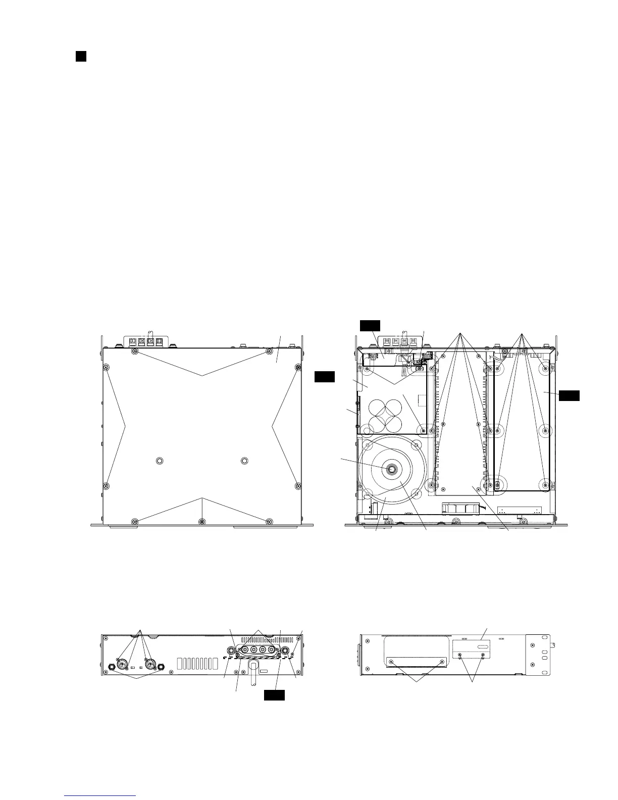
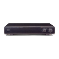
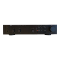
(Fig. 1)
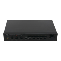
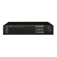
(Fig. 2)
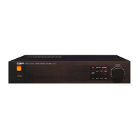
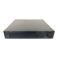
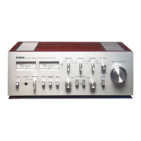
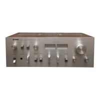
(Fig. 3) (Fig. 4)
[420]
[420] [420]
[420]
[420]: Bind Head Tapping Screw-B 4.0X8 MFZN2BL (EG340190)
[290]: Bonding Tapping Screw-B 3.0X8 MFZN2BL (VN413300)
[300]: Bind Head Tapping Screw-B 3.0X12 MFZN2BL (VQ074600)
[320]: Bind Head Tapping Screw-B 3.0X8 MFZN2BL (EP600190)
[103]: Bind Head Tapping Screw-B 4.0X8 MFZN2BL (EG340190)
[140]: Bind Head Tapping Screw-B 3.0X8 MFZN2BL (EP600190)
[80A]: Bind Head Screw A4.0X8 MFZN2BL (VP156800)
[120]: Bind Head Tapping Screw-B 3.0X8 MFZN2BL (EP600190)
[160]: Bonding Tapping Screw-B 4.0X8 MFZN2BL (VR779900)
[180]: Bind Head Tapping Screw-B 3.0X8 MFZN2BL (EP600190)
Top cover
<Top view>
<Rear view> <Side view>
[180][160]
IN
AC 3/6
AC 2/6
[290A] [320] [300] [320]
[A] [B]
[290B]
Speaker terminal cover
[B]
AC 3/6
[80A]
[120]
DB angle
DB angle
[140][103]
[C]
Transformer holder PA unitPower transformer
DISASSEMBLY PROCEDURE
CP2000
9
1. Top Cover (time required: about 3 minutes)
1-1 Remove the nine (9) screws marked [420]. The top cover
can then be removed. (Fig. 1)
2. IN Circuit Board (time required: about 8 minutes)
2-1 Remove the top cover. (See procedure 1.)
2-2 Remove the six (6) screws marked [180], the four (4) screws
marked [290A] and the two (2) hexagonal nuts marked [A].
The IN circuit board can then be removed. (Fig. 2, Fig. 3)
3. AC3/6 Circuit Board
(time required: about 10 minutes)
3-1 Remove the top cover. (See procedure 1.)
3-2 Remove the two (2) screws marked [320]. The speaker
terminal cover can then be removed. (Fig. 3)
3-3 Remove the screw marked [290B], the two (2) screws
marked [300] and the two (2) hexagonal nuts marked [B].
The AC3/6 circuit board can then be removed. (Fig. 3)
4. AC2/6 Circuit Board
(time required: about 15 minutes)
4-1 Remove the top cover. (See procedure 1.)
4-2 Remove the AC3/6 circuit board. (See procedure 3.)
4-3 Remove the screw marked [80A], the three (3) screws
marked [120] and the two (2) screws marked [140]. The
AC2/6 circuit board and the DB angle can then be removed.
(Fig. 2, Fig. 4)
5. Power Transformer
(time required: about 8 minutes)
5-1 Remove the top cover. (See procedure 1.)
5-2 Remove the two (2) screws marked [103] and the
hexagonal bolt marked [C]. The transformer holder and
the power transformer can then be removed. (Fig. 2, Fig. 4)