HOW THE SYNTHESIZER
WORKS
i
The synthesizer
consists of sound producing
and
sound modifying
circuits, all related by a nunnber
of
signal
paths
and
control
circuits.
Oscillators and Noise
Generators produce the raw ingredients for sounds.
Wave Shape Converters, Filters,
Amplifiers, a
Ring
Modulator,
a
Tremolo,
and
sub
oscillators further
modify
the sound
(the audio signals). These circuits,
plus
the
distinction
between audio and control
functions, are detailed below. While
voltages
are
discussed, it
is
not
really
necessary
to
understand how
voltages work;
when
you move the
controls
and
knobs,
you are
adjusting voltages
inside the synthesizer.
Audio Signals
&
Control Voltages
Electric
currents that flow through
synthesizers
can
be thought
of
in
two
categories:
audio signals and
control voltages.
The
audio signals
constitute
the
actual
sound
as it is generated, modified, and ultimately
fed
to
the output.
The control
voltages themselves
are
never
heard, but
are
instead
used
to
adjust the circuits
which process the audio.
Audio signals
are alternating currents
(AC)
with
fre-
quencies in
the audible range which,
as
you
probably
know,
covers about
10 octaves from
20 cycles per
second
(Hz)
to
20,000
cycles
per
second (Hz). Audio
signal
voltages
vary
at
different
points in the synthe-
sizer,
but
they
average
about 0.775 volts
at
the
output
when
the
rear panel
HIGH/LOW
switch is
at
HIGH
position
(OdBm into
600
ohms).
Control voltages
are
usually
10 volts
or
less, and
may
be
dc
(direct current)
or
AC
(alternating current).
AC
control
voltages vary
in frequency
from very
low,
sub-audio frequencies (1/2Hz)
up
to
the audio
fre-
quency
range
(as high
as
500Hz
or
more). The
effect
produced
by a
voltage
controlled
circuit
will vary in
proportion
to
the control
voltage applied.
For
example,
a
VCA
(voltage
controlled
amplifier)
will cause
the
audio signal
to be
higher
in volume
when the
control
voltage
is higher in level. If
a steady dc control
voltage
is applied
to
the VCA,
the volume
of
sound
coming
out
of the VCA
will increase
by a
proportionate amount
and will remain
at
that
level. If
an AC
control
voltage is
applied
to
the same
VCA,
then
the volume
will vary
up
and
down, corresponding
to
the variations
of
the
AC
voltage;
this is AM,
or amplitude
modulation.
When
a dc
voltage
is applied
to a VCO (voltage
controlled
oscillator),
the oscillator
increases its
frequency. When
an AC control
voltage is applied
to
a VCO,
the
frequency
varies
up and
down, producing
an
effect
known as
vibrato
or
FM
(frequency
modula-
tion).
Similarly,
when
AC
or dc
voltages
are applied
to
VCF's
(voltage
controlled filters), the filter character-
istics change;
the
cutoff
points
move
up
or
down.
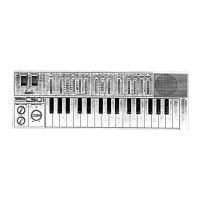
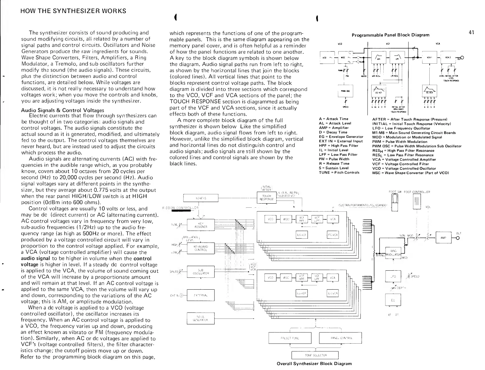
Refer
to
the
programming block
diagram
on this
page.
which represents
the
functions
of
one
of
the program-
mable
panels. This is the
same
diagram
appearing
on the
memory
pane! cover, and
is often
helpful
as a reminder
of
how
the panel functions
are
related
to
one another.
A
key
to
the
block diagram symbols is shown below
the
diagram. Audio
signal paths
run from left
to
right,
as
shown
by the horizontal lines
that join the
blocks
(colored lines). All vertical
lines
that point
to
the
blocks
represent control
voltage paths.
The block
diagram is divided
into three
sections which correspond
to
the
VCO,
VCF
and VCA
sections
of the panel; the
TOUCH
RESPONSE
section is
diagrammed
as being
part
of
the VCF and VCA
sections, since
it actually
effects
both of these functions.
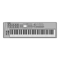
A more complete block
diagram
of
the
full
synthesizer is shown
below Like
the simplified
block
diagram, audio signal flows
from left
to
right.
However,
unlike the simplified block
diagram, vertical
and horizontal lines
do not distinguish control and
audio signals; audio signals
are
still shown
by
the
colored lines and control
signals are shown by the
black lines.
Programmable
Panel Block
Diagram
41
n r
j1_
W
/r T^
Wi\
-tz^
Wf
I Al
A
D
N INITIAI. AHiR
8flH.LlAMCE
TOUCH
Rf Sf>tlNS(
'TuO
^m
u^
m
A C S R
A
=
Attack Time
AL
=
Attack
Level
AMP
=
Amplifier
D
=
Decay Time
EG
=
Envelope Generator
EXT IN
=
External Input
HPF
=
High
Pass
Filter
IL
=
Initial
Level
LPF
=
Low
Pass
Filter
PW
=
Pulse
Width
R
=
Release Time
S
=
Sustain Level
TUNE
=
Pitch Controls
R 3
30NC0N!R0LlER
MTIAL-.
AFTEfl'
SLBVC
TOUCH
RESPOKSF
AB.PB'i
1
*
y
AFTER
=
After Touch
Response
(Pressure)
INITIAL
=
Initial Touch
Response (Velocity)
LFO
-
Low Frequency
Oscillator
M1-M8
=
Main Sound Generating Circuit Boards
MOD
=
Modulation or Modulated Signal
PWM
=
Pulse Width Modulation
PWM OSC
=
Pulse Width Modulation Sub
Oscillator
RESh
=
High
Pass Filter
Resonance
RESl
=
Low
Pass Filter Resonance
VCA
=
Voltage Controlled Amplifier
VCF
=
Voltage Controlled Filter
VCO
=
Voltage Controlled Oscillator
WSC
=
Wave Shape Converter (Part of
VCO)
FOOT
SW
FOOT
CONTROl^LR
SU"..Airj,p!jRTA.yENT0/Gi_6SAN[)0;
high/—
splfdJ^^
KFYHOARD
CONTROL
m
m
VCf
:HP[ .:
-
,'"pr;.
vc:a
-
LGvCI
FG
VCA
M
Jj..J'^:v.,U
-r-
OCT
AMP
I
O
SUB
OSCILLATOR
c
ci
.
;V
T
N
(py-
FX'FR\Al
/T^Pao
v^
DEP
Overall Synthesizer Block Diagram
 Loading...