20
DBR10/DBR12/DBR15
C-7. VSL Circuit Board (P destination only)
(Time required: About 4 minutes)
C-7-1 Remove the shield AMP assembly. (See procedure C-2.)
C-7-2 Remove the SUBL(ACIN) circuit board.
(See procedure C-5.)
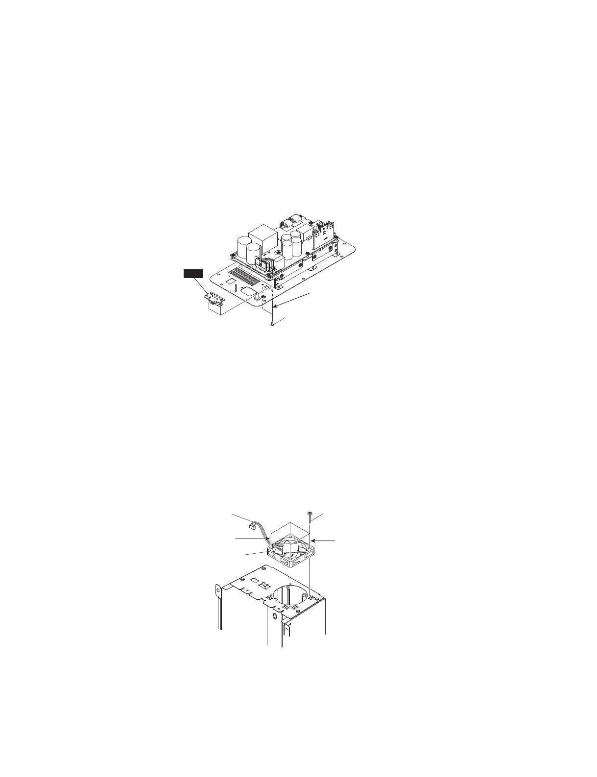
C-7-3 Remove the two (2) screws marked [190]. The VSL
circuit board can then be removed. (Fig. C-6)
* When installing the VSL circuit board, fi rst tighten the
priority screw as shown in Fig. C-6.
C-8. DC FAN (Time required: About 1 minute)
C-8-1 Remove the four (4) screws marked [370]. The DC fan
can then be removed. (Fig. C-7)
* When installing the DC fan,
first tighten the two (2)
priority screws in order as shown in Fig. C-7.
* Check the color of connector assembly in DC fan.
AMP ASSEMBLY 10 : Red (hot), Black (cold)
AMP ASSEMBLY 12/15 : White (hot), Black (cold)
C-7. VSLシート(P仕向けのみ)
(所要時間:約4分)
C-7-1 シールドAMP組立を外します。(C-2項参照)
C-7-2 SUBL(ACIN)シートを外します。(C-5項参照)
C-7-3 [190]のネジ2本を外して、VSLシートを外します。
(図C-6)
※ AMPSシートを取り付け時には、図に示す優先ネジを先
に締めてください。(図C-6)
C-8. DCファン
(所要時間:約1分)
C-8-1 [370]のネジ4本を外して、DCファンを外します。
(図C-7)
※ DCファンを取り付け時には、優先ネジ2本を図に示す順
番で先に締めてください。(図C-7)
※ DCファンの束線の色を確認します。
AMP組立10:赤(hot)、黒(cold)
AMP組立12/AMP組立15:白(hot)、黒(cold)
>@
VSL
35,25,7<6&5(:
(優先ネジ)
Fig. C-6
(図C-6)
Fig. C-7
(図C-7)
>@
35,25,7<6&5(:QG
(優先ネジ 2)
35,25,7<6&5(:VW
(優先ネジ 1)
'&)$1
(DC ファン)
'&)$1&211(&725$66(0%/<
(DC ファン束線)
 Loading...