SERVICE MANUAL
HAMAMATSU, JAPAN
SERVICE MANUAL
Copyright (c) Yamaha Corporation. All rights reserved. PDF ’14.07
012126
PA
INSPECTIONS(検査) ......................................... 44
UPDATING(アップデート) ................................. 51
MODEL ID SETTING(モデル ID 設定) .............. 53
STARTING SEQUENCE(起動シーケンス) .. 54/56
FINISHING SEQUENCE(終了シーケンス) .. 58/59
PARTS LIST
BLOCK DIAGRAM
(ブロックダイアグラム)
LEVEL DIAGRAM(レベルダイアグラム)
CIRCUIT DIAGRAM(回路図)
SPECIFICATIONS(総合仕様) .............................. 3
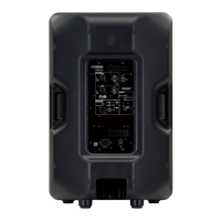
PANEL LAYOUT(パネルレイアウト) ................... 4
CIRCUIT BOARD LAYOUT
(ユニットレイアウト) ............................................... 5
DIMENSIONS(寸法図) ......................................... 7
DISASSEMBLY PROCEEDURE(分解手順) ...... 8
LSI PIN DESCRIPTION(LSI 端子機能表) ......... 21
CIRCUIT BOARDS(シート基板図) .................... 22
TEST PROGRAM(テストプログラム) ............... 29
NOTES ON THE MEASUREMENT ENVIRONMENT
(測定環境に対する注意事項) .................................. 42
CONTENTS(目次)
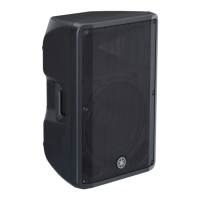
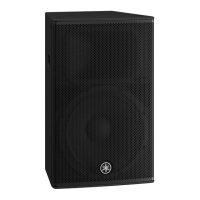
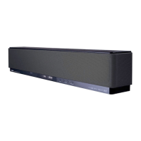
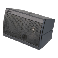
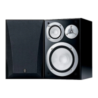
32:(5('63($.(56<67(0
'%5VHULHV
DBR15DBR12
DBR10