19
DBR10/DBR12/DBR15
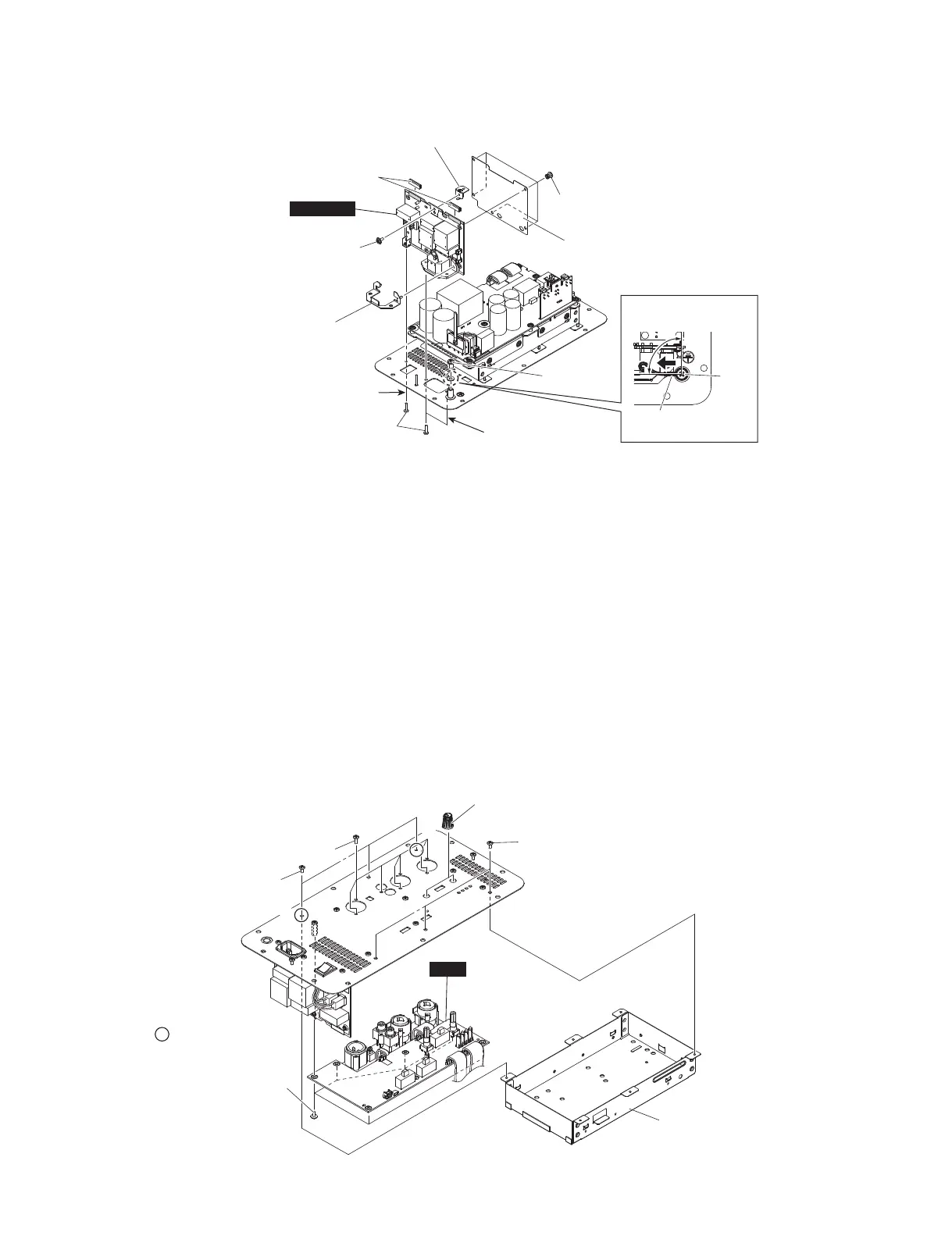
C-6. DSP Circuit Board
(Time required: About 5 minutes)
C-6-1 Remove the shield AMP assembly. (See procedure C-2.)
C-6-2 Remove the six (6) screws marked [180]. The shield
DSP assembly can then be removed. (Fig. C-5)
* When installing the shield DSP assembly, first tighten
the two (2) priority screws in order as shown in Fig. C-5.
C-6-3 Remove the two (2) knob VR small. (Fig. C-5)
C-6-4 Remove the seven (7) screws marked [30] and seven (7)
screws marked [200]. The DSP circuit board can then
be removed. (Fig. C-5)
* After replacing the DSP circuit board, be sure to execute
setting of the model ID.
For details, refer to "MODEL ID SETTING".
(See page 53)
>@
>@
w
q
35,25,7<6&5(:
(優先ネジ)
DSP
>@
>@
.12%9560$//
(ノブ VR 小)
6+,(/''63$66(0%/<
(シールド DSP 組立)
C-6. DSPシート
(所要時間:約5分)
C-6-1 シールドAMP組立を外します。(C-2項参照)
C-6-2 [180]のネジ6本を外して、シールドDSP組立を外
します。(図C-5)
※ シールドDSP組立を取り付け時には、優先ネジ2本を図
に示す順番で先に締めてください。(図C-5)
C-6-3 ノブVR小2個を外します。(図C-5)
C-6-4 [30]の ネ ジ7本 と[200]の ネ ジ7本を外して、DSP
シートを外します。(図C-5)
※ DSPシートを交換した際は、必ずモデルIDの設定を実施
してください。
詳細は、「モデルID設定」を参照してください。
(53ページ参照)
Fig. C-4
(図C-4)
Fig. C-5
(図C-5)
>@
>@
>@
>@
>@
SUB
(
ACIN
)
&29(5$&,1
(カバー ACIN)
$1*/($&,1
(取付板 ACIN)
121:29(1
)$%5,&&/27+
(不織布)
%5$&.(7$&,1/(7
(ブラケットACインレット)
35,25,7<6&5(:QG
(優先ネジ 2)
7(50,1$//8*
(ターミナルラグ)
GHJUHH
(90 度)
35,25,7<6&5(:VW
(優先ネジ 1)
 Loading...