11
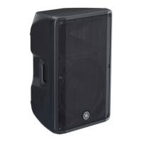
DBR10/DBR12/DBR15
35,25,7<6&5(:
(優先ネジ)
>@
>@
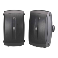
%$))/($66(0%/<
(バッフル 10 組立)
+)&211(&725
$66(0%/<<(//2:
(WC 組立 HF10 束線黄(+))
%5$&.(7+)3
(取付板 HFP)
/28'63($.(57:((7(5
(スピーカ(ツイーター))
5('0$5.,1*
(赤マーク)
+)&211(&725
$66(0%/<%/8(²
(WC 組立 HF10 束線青(−))
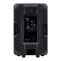
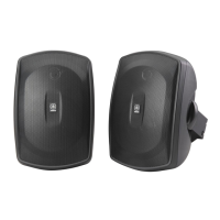
A-5. Amp Assembly 10
(Time required: About 3 minutes)
A-5-1 Remove the ten (10) screws marked [250].
(Fig. A-9,Fig. A-10)
* When installing the amp assembly 10,
fi rst tighten the
two (2) priority screws in order as shown in Fig. A-10
.
A-5-2 Loosen the two (2) screws for removing the amp
assembly. (Fig. A-10)
* Loosen only ! Never remove these screws. Tighten
these screws when installing the amp assembly 10.
(Fig. A-10)
A-5-3 Hold the two (2) screws for removing the amp assembly
and then remove the amp assembly 10 carefully.
(Fig. A-10)
For about disassembly of amp assembly, refer to 17
page.
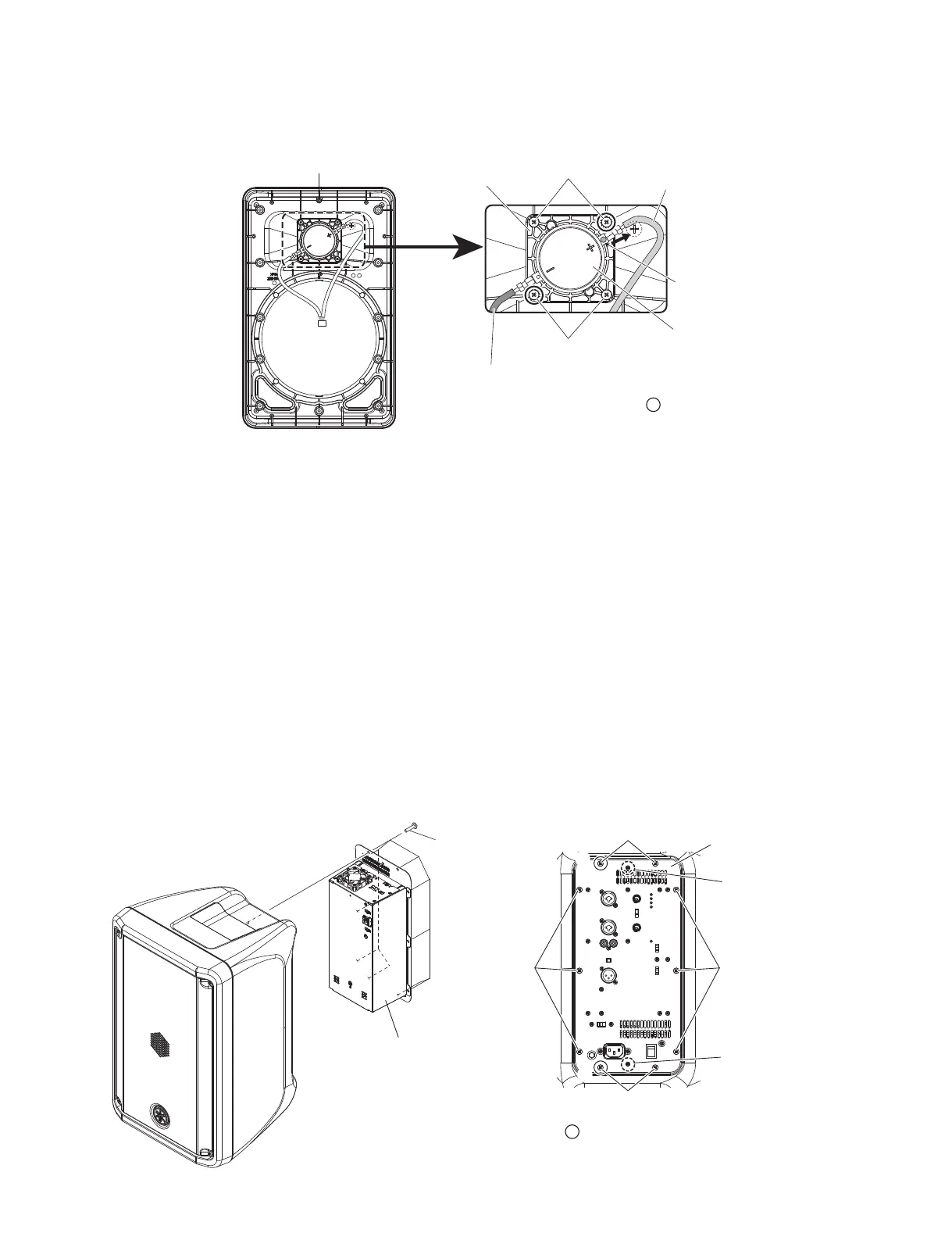
35,25,7<6&5(:
(優先ネジ)
>@ >@
>@
>@
$03$66(0%/<
(アンプ組立 10)
6&5:()255(029,1*
7+($03$66(0%/<
(アンプ組立取り外し用ネジ)
6&5:()255(029,1*
7+($03$66(0%/<
(アンプ組立取り外し用ネジ)
w
q
>@
$03$66(0%/<
(アンプ組立 10)
Fig. A-8
(図A-8)
Fig. A-9
(図A-9)
Fig. A-10
(図A-10)
A-5. アンプ組立 10
(所要時間:約 3 分)
A-5-1 [250] のネジ 10 本を外します。(図 A-9、図 A-10)
※ アンプ組立 10 を取り付けるときは、優先ネジ 2 本を図
に示す順番で先に締めてください。(図 A-10)
A-5-2 アンプ組立取り外し用ネジ 2 本を緩めます。
(図 A-10)
※ これらのネジは緩めるだけで、外さないように注意して
ください。アンプ組立 10 取り付け時には、これらのネ
ジを締めてください。(図 A-10)
A-5-3 アンプ組立取り外し用ネジ 2 箇所を持って、慎重
にアンプ組立 10 を外します。(図 A-10)
アンプ組立の分解手順は、17 ページを参照してく
ださい。
 Loading...