9
DBR10/DBR12/DBR15
/)&211(&725
$66(0%/<5('%/$&.
(WC 組立 LF10 束線(赤/黒))
+)&211(&725
$66(0%/<<(//2:%/8(
(WC 組立 HF10 束線(黄/青))
%$))/($66(0%/<
(バッフル 10 組立)
>@
>@
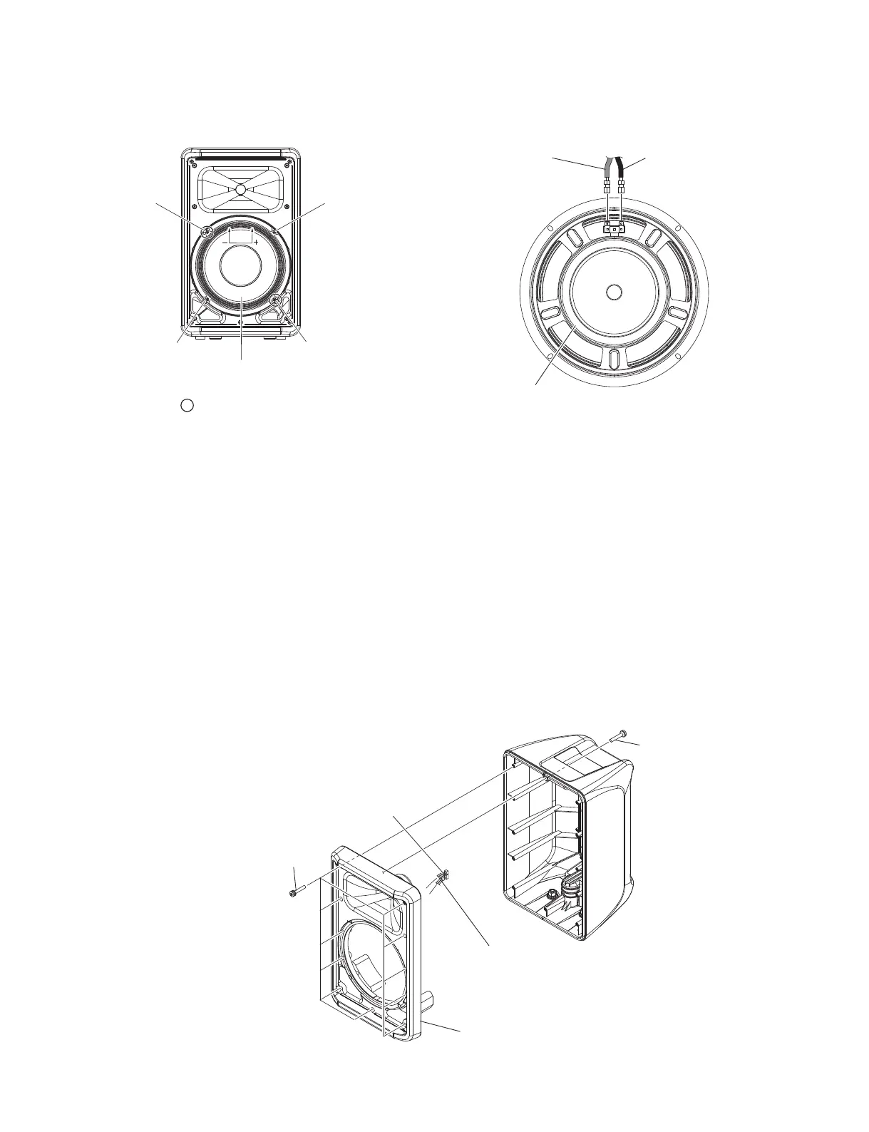
A-3. Baffl e 10 Assembly
(Time required: About 4 minutes)
A-3-1 Remove the grille 10 assembly. (See procedure A-1.)
A-3-2
Remove the loud speaker (woofer). (See procedure A-2.)
A-3-3 Remove the twelve (12) screws marked [170]. The
baffl e 10 assembly can then be removed.
(Fig. A-5, Fig. A-6)
*
When installing the baffl e 10 assembly, fi rst tighten the
seven (7) priority screws in order as shown in Fig. A-6.
A-3-4 Disconnect the connectors of the LF 10 connector
assembly (red/black), HF 10 connector assembly
(yellow/blue) from the amp assembly 10.
(Fig. A-5, Photo A-1)
* Take care not to open the baffle 10 assembly
too wide or these connector assemblies may be
damaged. (Fig. A-5, Photo A-1)
Fig. A-3
(図A-3)
Fig. A-4
(図A-4)
>@
>@
>@
/28'63($.(5:22)(5
(スピーカ(ウーファー))
>@
35,25,7<6&5(:
(優先ネジ)
/)&211(&725
$66(0%/<5('
(WC 組立 LF10 束線赤(+))
/)&211(&725
$66(0%/<%/$&.²
(WC 組立 LF10 束線黒(−))
/28'63($.(5:22)(5
(スピーカ(ウーファー))
Fig. A-5
(図A-5)
A-3. バッフル 10 組立
(所要時間:約 4 分)
A-3-1 グリル 10 組立を外します。(A-1 項参照)
A-3-2 スピーカ(ウーファー)を外します。(A-2 項参照)
A-3-3 [170] のネジ 12 本を外して、バッフル 10 組立を
外します。(図 A-5、図 A-6)
※ バッフル 10 組立を取り付けるときは、優先ネジ 7 本を
図に示す順番で先に締めてください。(図 A-6)
A-3-4 アンプ組立 10 から WC 組立 LF10 束線(赤/黒)、
WC 組立 HF10 束線(黄/青)のコネクターを
外します。(図 A-5、写真 A-1)
※ バッフル 10 組立を開きすぎて、これらの束線を傷めな
いように注意してください。(図 A-5、写真 A-1)