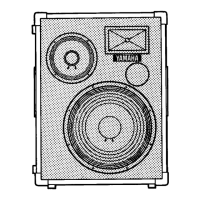
44
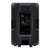
DBR10/DBR12/DBR15
This test specifi cation is applied to the AMP assembly 10/12/15.
1. Measurement Conditions
1-1. Measuring Instrument and jigs
• Use a reliable measuring device capable of precisely
measuring the specification values indicated in this
document.
• Input impedance of the measuring instrument should
be more than 100 kΩ.
• Use the 22kHz low pass fi lter for the measurement of
the noise, total harmonic distortion, maximum output
and analog mute.
• Serial Interface Jig set for diagnosis :
ZF928400/ZF928401 (USB2UART-CP2102 x 1,
4pin cable x 1)
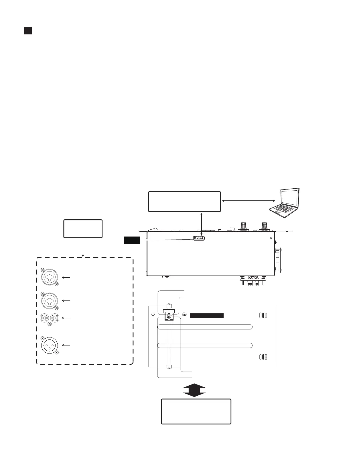
1-2. Connection
Perform connection as shown in the fi gure below.
この検査規格はアンプ Assy10/12/15 に適用されます。
1. 測定条件
1-1. 測定器、治具
•
検査に使用する測定器は、本文中に記載の規格を
十分精度良く測定できる精度及び確度を持つもの
を使用してください。
•
測定器の入力インピーダンスは 100k Ω以上の
ものを使用してください。
• ノイズ、全高調波歪率、最大出力、アナログ
MUTE の測定には 22kHz のローパスフィルタ
を使用してください。
•
ダイアグ用
シリアルインターフェイス治具セット:
ZF928400/ZF928401(USB2UART-CP2102 ×1、
4 ピンケーブル×1)
1-2. 接続
下図のように接続します。
INSPECTIONS
(検査)
$03$66(0%/<
$03$66(0%/<
3
3&
6HULDO,QWHUIDFH-LJ
(シリアルインターフェース治具)
=)=)
3
&1
3
6:
'63
SLQ6,*1$/(1ピン:信号)
SLQ*1'(2ピン:GND)
(CN304)
SLQ6,*1$/(4ピン:信号)
SLQ*1'(3ピン:GND)
ї
ї
+) +)
/) /)
3$1(/
,13877(50,1$/;/5
(入力端子1(XLR))
,13877(50,1$/;/5
(入力端子2(XLR))
,13877(50,1$/3,16
(入力端子3(PINS))
2873877(50,1$/;/5
(出力端子(XLR))
,27(50,1$/(入出力端子)
6LJQDO*HQHUDWRU
(信号発生器)
2VFLOORVFRSH(オシロスコープ)
/HYHO0HWHU(レベルメーター)
'LVWRUWLRQ0HWHU(歪率計)
)LOWHU(フィルタ)(AUX-0025)
SLQFDEOH
(4 ピンケーブル)
86%8$57&RQYHUVLRQ
(USB-UARTシート)
86%8$57&3
SUBL
(SP OUT)