49
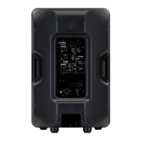
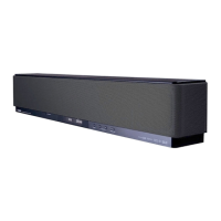
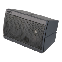
DBR10/DBR12/DBR15
2-13.
Total Harmonic Distortion
(1) Set the VOL1:MAX, VOL2:MIN, LINE/MIC:LINE,
THRU/MIX:THRU.
When the signal is input to the INPUT terminal 1 (XLR).
The following outputs are obtained, total harmonic
distortion is measured.
CN304-1(OUTHF+), CN304-2(OUTHF-)
+11.24±0.5 dBu : THD+N=0.2% or less.
(2) Set the VOL1:MAX, VOL2:MIN, LINE/MIC:MIC,
THRU/MIX:THRU.
When the signal is input to the INPUT terminal 1 (XLR).
The following outputs are obtained, total harmonic
distortion is measured.
CN304-4(OUTLF+), CN304-3(OUTLF-)
+8.24±0.5dBu : THD+N=0.5% or less.
(3) Set the VOL1:MIN, VOL2:MAX, LINE/MIC:LINE,
THRU/MIX:MIX.
When the signal is input to the INPUT terminal 2 (XLR).
The following outputs are obtained, total harmonic
distortion is measured.
JK601(OUTPUT)
+10.00±0.5dBu : THD+N=0.2% or less.
2-14.
Maximum Output
Set the VOL1:MIN, VOL2:MAX, LINE/MIC:LINE,
THRU/MIX:THRU.
(1) When the signal of 100 Hz is input to the INPUT
terminal 2 (XLR).
The following outputs are obtained, total harmonic
distortion is measured.
DBR15/DBR12
CN304-4(OUTLF+)
+33.0 dBu
+0.2 dBu
CN304-3(OUTLF-) -0 dBu
: THD+N=1 % or less.
DBR10
CN304-4(OUTLF+)
+31.3dBu
+0.2 dBu
CN304-3(OUTLF-) -0 dBu
: THD+N=1 % or less.
(2) When the signal of 5 kHz is input to the INPUT
terminal 2 (XLR).
The following outputs are obtained, total harmonic
distortion is measured.
CN304-1(OUTHF+)
+28.3dBu
+0.2 dBu
CN304-2(OUTHF-) -0 dBu
: THD+N=1 % or less.
(3) When the signal of 1 kHz is input to the INPUT
terminal 2 (XLR).
The following outputs are obtained, total harmonic
distortion is measured.
JK601(OUTPUT) +17.0dBu +0.2 dBu
-0 dBu
: THD+N=1 % or less.
* Measure this inspection within 5 seconds.
* Measure each output individually.
2-13.
全高調波歪率測定
(1) VOL1: 最 大、VOL2: 最 小、LINE/MIC:LINE、
THRU/MIX:THRU に設定します。
入力端子 1(XLR)に信号を入力します。
以下の出力を得た時、全高調波歪率を測定します。
CN304-1(OUTHF+)、CN304-2(OUTHF-)
+11.24 ± 0.5dBu :THD+N=0.2% 以下
(2) VOL1: 最 大、VOL2: 最 小、LINE/MIC:MIC、
THRU/MIX:THRU に設定します。
入力端子 1(XLR)に信号を入力します。
以下の出力を得た時、全高調波歪率を測定します。
CN304-4(OUTLF+)、CN304-3(OUTLF-)
+8.24 ± 0.5dBu :THD+N=0.5% 以下
(3) VOL1: 最 小、VOL2: 最 大、LINE/MIC:LINE、
THRU/MIX:MIX に設定します。
入力端子 2(XLR)に信号を入力します。
以下の出力を得た時、全高調波歪率を測定します。
JK601(OUTPUT)
+10.00 ± 0.5dBu :THD+N=0.2% 以下
2-14.
最大出力
VOL1: 最小、VOL2: 最大、LINE/MIC:LINE、
THRU/MIX:MIX に設定します。
(1) 入力端子 2(XLR)に 100Hzの信号を入力します。
以下の出力を得た時、全高調波歪率を測定します。
DBR15/DBR12
CN304-4(OUTLF+)
+33.0dBu
+0.2dBu
CN304-3(OUTLF-) -0dBu
:THD+N=1%以下
DBR10
CN304-4(OUTLF+)
+31.3dBu
+0.2dBu
CN304-3(OUTLF-) -0dBu
:THD+N=1%以下
(2) 入力端子 2(XLR)に 5kHzの信号を入力します。
以下の出力を得た時、全高調波歪率を測定します。
CN304-1(OUTHF+)
+28.3dBu
+0.2dBu
CN304-2(OUTHF-) -0dBu
:THD+N=1%以下
(3) 入力端子 2(XLR)に 1kHzの信号を入力します。
以下の出力を得た時、全高調波歪率を測定します。
JK601(OUTPUT) +17.0dBu +0.2dBu
-0dBu
:THD+N=1%以下
※この検査は 5 秒以内に測定してください。
※各出力を個別に測定してください。