42
DBR10/DBR12/DBR15
1. Insert AUX-0025 between classD amplifier and the
audio analyzer when you measure classD amplifier.
* Reason to which insertion of the Audio Precision AUX-0025 is
indispensable.
The high frequency noise caused by the switching drive is included
in the output signal of classD amplifi er.
However, the audio analyzer doesn't generally assume the high
frequency. In a word, there is no tolerance to the high frequency.
Therefore, there is a possibility that the audio analyzer doesn't
operate normally when the high frequency is not removed with
AUX-0025.
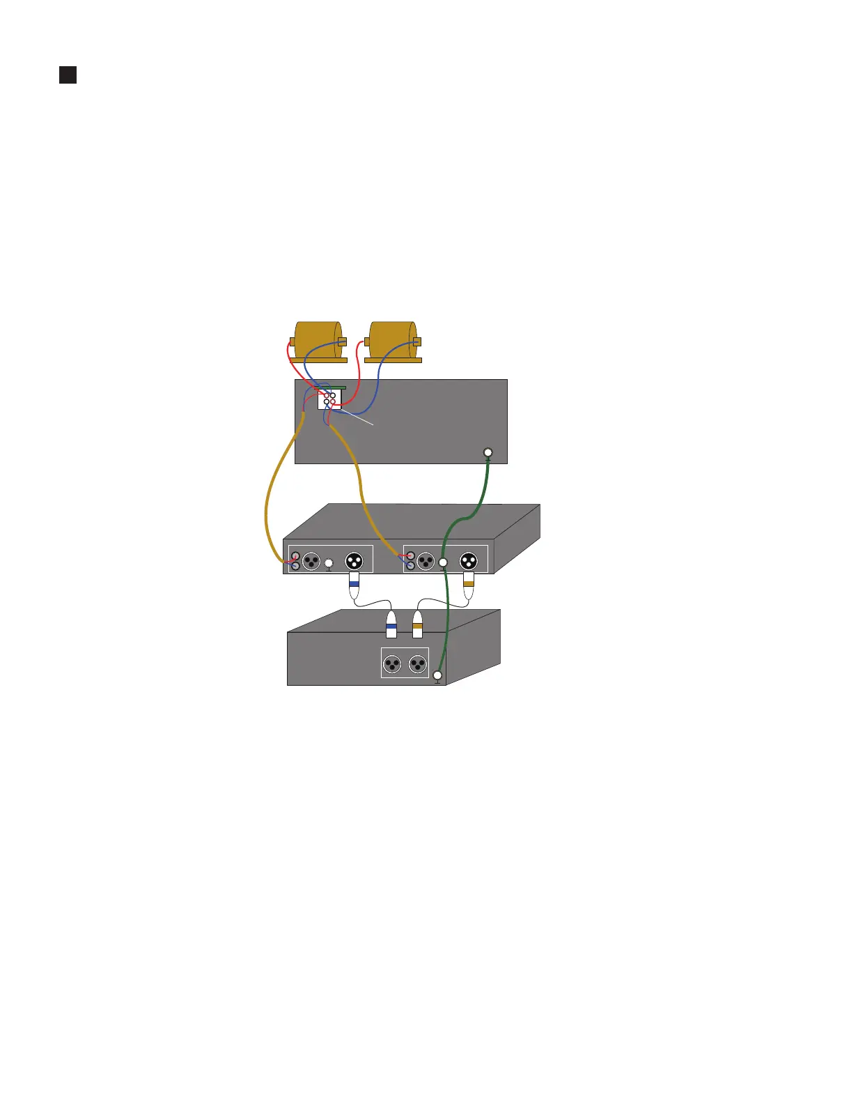
2. The reason to recommend the connection method
of “Fig. 1”
The “Fig. 2” is a block chart of the output composition of the AMP
assembly of DBR.
The output of the AMP assembly of DBR is single-ended, but
generally the output of D class amplifi er is not necessarily a single-
ended output.
The output method of a recent classD amplifi er takes various forms.
Therefore, the connection method with the interchangeability that
can correspond to any amplifi er output method is preferable.
The connection method of “Fig. 1” can be compatible for the
amplifi er output with the single-ended output and the bridge output,
and apply any audio analyzer.
Please shorten between the amplifier to be measured and the
analyzer to suppress the infl uence of turbulence and connect it.
Moreover, please make to fl oating without fail for the output.
(One on the load side is not grounded. When monitoring with the
oscilloscope, it does based on the chassis playground. )
The AMP assembly of DBR is using class D amplifi er.
NOTES ON THE MEASUREMENT ENVIRONMENT(測定環境に対する注意事項)
Dummy Load
䞉APX SERIES
䞉SYSTEM ONE
䞉SYSTEM TWO
䞉ATS-2
䞉VP-7722A etc
CH1 CH2
ANALOG INPUT
CHANNEL A
ANALOG OUTPUTANALOG OUTPUT
CHANNEL B
Ground wire
Balanced type shield wire
ANALOG INPUT
Analog input
AUDIO ANALYZER
AUX-0025
(Filter)
㻭㻺㻭㻸㻻㻳㻌㻵㻺㻼㼁㼀
㻸㻲
㻴㻲
㻻㼁㼀㻼㼁㼀
AMP ASSY of DBR
Fig. 1
(図1)
ConnectioncharttheclassDamplifier(AMPASSY15/12/10)ismeasured
(D級アンプ(AMPAss'y15/12/10)のオーディオ性能測定時の推奨接続図)
1. D級アンプを測定するときは必ずD級アンプとオディ
オアナライザの間にAUX-0025を挿入してください。
※ AudioPrecision社AUX-0025の挿入が必須である理由
D級アンプの出力信号にはスイッチング駆動で生じた高周
波ノイズが含まれています。
しかし、一般的にオーディオアナライザは可聴帯域外の高周
波を想定して設計されていないため高周波ノイズに対する
耐性がありません。
したがって、AUX-0025 などのパッシブフィルタで高周波を
除去しないと、オーディオアナライザが正常に動作しない可
能性があります。
2.(図1)の接続方法を推奨する理由について
(図2)はDBRアンプユニットの出力構成のブロック図です。
DBRアンプユニットはシングルエンド出力ですが、一般的に
D級アンプの出力は必ずしもシングルエンド出力だとは限り
ません。
最近のD級アンプの出力方式は様々な形態をとっています。
したがって、どのようなアンプ出力方式にも対応できる互換性
のある接続方法が望ましいです。
(図1)の接続方法は、シングルエンド出力やブリッジ出力をも
つアンプ出力に対して互換性があり、どのようなオーディオア
ナライザでも適用できます。
外乱の影響をできる限り排除するために、被測定アンプとアナ
ライザの筺体間を短くして接続してください。
また、出力は必ずフローティングにして測定してください。
(負荷側の片方を接地しないでください。オシロスコープでモ
ニタするときは、シャーシグランドを基準にして行います。)
DBRアンプユニットはD級アンプを使用しています。
 Loading...