48
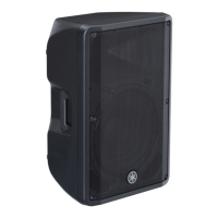
DBR10/DBR12/DBR15
2-12.
Frequency Response
(1) Set the VOL1:MAX, VOL2:MIN, LINE/MIC:LINE,
THRU/MIX:THRU.
The signal of -10 dBu is input to INPUT terminal 1
(XLR), and the output voltage is measured.
Measurements are recorded.
CN304-1(OUTHF+) :
(A)
CN304-2(OUTHF-) :
The signal of 20Hz,-10dBu is input to INPUT
terminal 1 (XLR), and the output voltage is measured.
The range of -1.5±2.0dB based on A.
The signal of 20kHz,-10dBu is input to INPUT
terminal 1 (XLR), and the output voltage is measured.
The range of -0.5±2.0dB based on A.
(2) Set the VOL1:MAX, VOL2:MIN, LINE/MIC:MIC,
THRU/MIX:THRU.
The signal of -42 dBu is input to INPUT terminal 1
(XLR), and the output voltage is measured.
Measurements are recorded.
CN304-4(OUTLF+) :
(B)
CN304-3(OUTLF-) :
The signal of 20Hz,-42dBu is input to INPUT
terminal 1 (XLR), and the output voltage is measured.
The range of-2.0±2.0dB based on B.
The signal of 20kHz,-42dBu is input to INPUT
terminal 1 (XLR), and the output voltage is measured.
The range of -1.0±2.0dB based on B.
(3) Set the VOL1:MIN, VOL2:MAX, LINE/MIC:LINE,
THRU/MIX:THRU.
The signal of -10 dBu is input to INPUT terminal 2
(XLR), and the output voltage is measured.
Measurements are recorded.
JK601(OUTPUT) : (B)
The signal of 20Hz,-10dBu is input to INPUT
terminal 2 (XLR), and the output voltage is measured.
The range of -0.2±2.0dB based on C.
The signal of 20kHz,-10dBu is input to INPUT
terminal 2 (XLR), and the output voltage is measured.
The range of -0.2±2.0dB based on C.
2-12.
周波数特性
(1) VOL1: 最 大、VOL2: 最 小、LINE/MIC:LINE、
THRU/MIX:THRU に設定します。
入力端子 1(XLR)に -10dBu の信号を入力し、
出力電圧を測定します。
測定値を記録します。
CN304-1(OUTHF+) :
(A)
CN304-2(OUTHF-) :
入力端子 1(XLR)に 20Hz、-10dBu の信号を入
力し、出力電圧を測定します。
Aを基準に -1.5 ± 2.0dBの範囲内であることを
確認します。
入力端子 1(XLR)に 20kHz、-10dBu の信号を
入力し、出力電圧を測定します。
Aを基準に -0.5 ± 2.0dBの範囲内であることを
確認します。
(2)VOL1: 最 大、VOL2: 最 小、LINE/MIC:MIC、
THRU/MIX:THRU に設定します。
入力端子 1(XLR)に -42dBu の信号を入力し、
出力電圧を測定します。
測定値を記録します。
CN304-4(OUTLF+) :
(B)
CN304-3(OUTLF-) :
入力端子 1(XLR)に 20Hz、-42dBu の信号を入
力し、出力電圧を測定します。
Bを基準に -2.0 ± 2.0dBの範囲内であることを
確認します。
入力端子 1(XLR)に 20kHz、-42dBu の信号を
入力し、出力電圧を測定します。
Bを基準に -1.0 ± 2.0dBの範囲内であることを
確認します。
(3) VOL1: 最 小、VOL2: 最 大、LINE/MIC:LINE、
THRU/MIX:MIX に設定します。
入力端子 2(XLR)に -10dBu の信号を入力し、
出力電圧を測定します。
測定値を記録します。
JK601(OUTPUT) :(C)
入力端子 2(XLR)に 20Hz、-10dBu の信号を入
力し、出力電圧を測定します。
Cを基準に -0.2 ± 2.0dB の範囲内であることを
確認します。
入力端子 2(XLR)に 20kHz、-10dBu の信号を
入力し、出力電圧を測定します。
Cを基準に -0.2 ± 2.0dB の範囲内であることを
確認します。

 Loading...