RX-V2400/RX-V2400RDS/DSP-AX2400
RX-V1400/RX-V1400RDS/HTR-5690/DSP-AX1400
RX-V2400/RX-V2400RDS/DSP-AX2400
RX-V1400/RX-V1400RDS/HTR-5690/DSP-AX1400
22
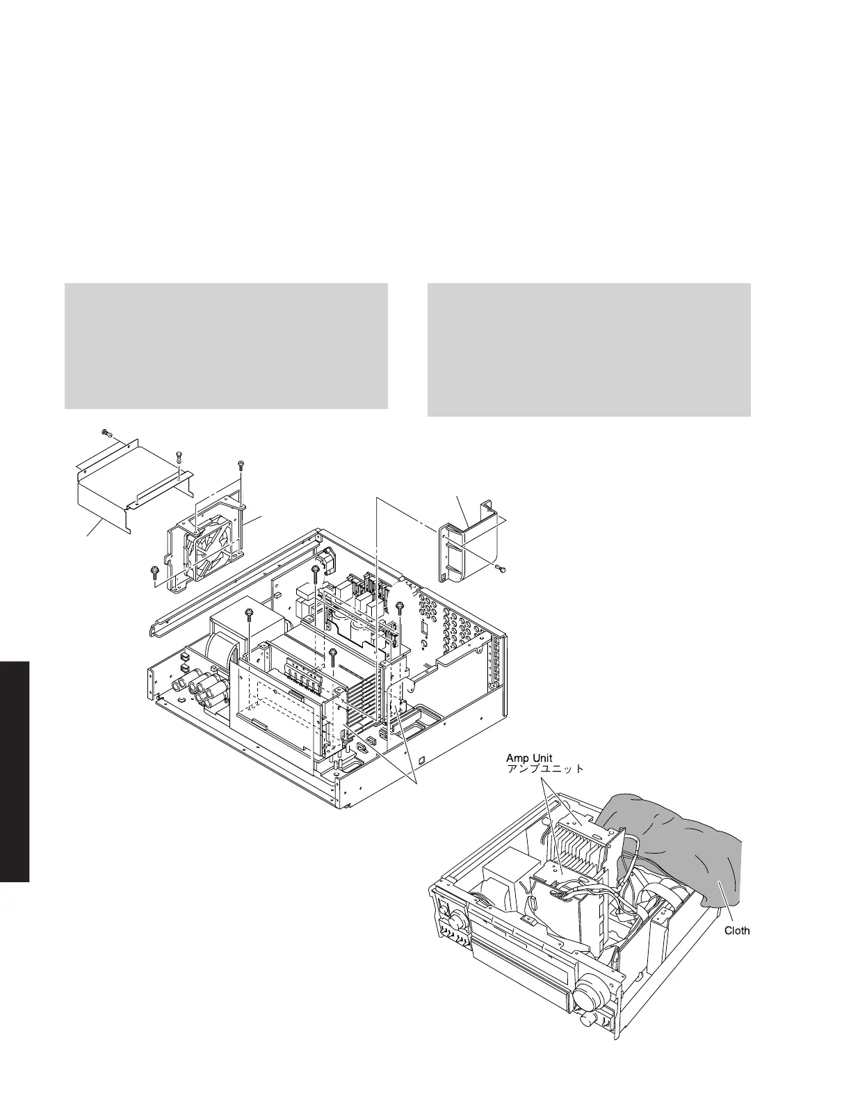
7. Removal of Fan
a. Remove 4 push rivets (D) and then remove the Cover.
(Fig. 6)
b. Remove 2 screws (E) and 2 screws (F). (Fig. 6)
c. Remove the Fan together with the frame by lifting them
up. (Fig. 6)
8. Removal of Amp Unit
a. Remove 2 push rivets (G) and then remove the Duct.
(Fig. 6)
b. Remove 4 screws (H) and 4 screws (I). (Fig. 6)
c. Remove the Amp Unit. (Fig. 6)
Fig. 6
7. ファンの外し方
8. アンプユニットの外し方
Fan
Cover
Duct
F
E
D
D
G
H
H
I
I
Amp Unit
When checking the Amp Unit:
• Put the Amp Unit together with the heat sink upright
on the art base and check them.
• Reconnect all cables (connectors) that have been
disconnected.
• When connecting the flat cable, use care for the
polarity.
アンプユニットをチェックする場合には
Fig. 7
Amp Unit
Cloth
 Loading...

