EasyManuals Logo

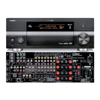
Yamaha DSP-AX2400 User Manual

Yamaha DSP-AX2400
147 pages
To Next Page IconTo Next Page
To Previous Page IconTo Previous Page
Page #55 background imageLoading...
Page #55 background image
RX-V2400/RX-V2400RDS/DSP-AX2400
RX-V1400/RX-V1400RDS/HTR-5690/DSP-AX1400
55
RX-V2400/RX-V2400RDS/DSP-AX2400
RX-V1400/RX-V1400RDS/HTR-5690/DSP-AX1400
No. Name I/O Function
 
  
 
  
  
 
 
  
  
   
  
  
  
  
  
  
   
  
  
   
  
  
  
   
  
  
  
  
  
  
  
   
   
   
   
  
  
   
   
   
   
  
  
   
   
   
   
   
IC509: LC89057W-VF4-E (DSP P.C.B)
Digital Audio Interface Transceiver
1) Input/output I or O = -0.3 to 3.6V, Is = -0.3 to 5.5V
2) Pins 32 and 33 are latch address setting input pins when pin 41 = "L".
3) Pin 34 is a demodulation function master or slave setting input pin when pin 41 = "L".
4) Pin 35 is a modulation function or general-purpose I/O function switch setting input pin when pin 41 = "L".
5) Perform ON/OFF for all power supplies with the same timing as a latch-up countermeasure.

Questions and Answers:

Question and Answer IconNeed help?

Do you have a question about the Yamaha DSP-AX2400 and is the answer not in the manual?

Yamaha DSP-AX2400 Specifications

General IconGeneral
BrandYamaha
ModelDSP-AX2400
CategoryReceiver
LanguageEnglish

Related product manuals