A
1
2
3
4
5
6
7
8
9
10
BCDEFGH I JK
L MN
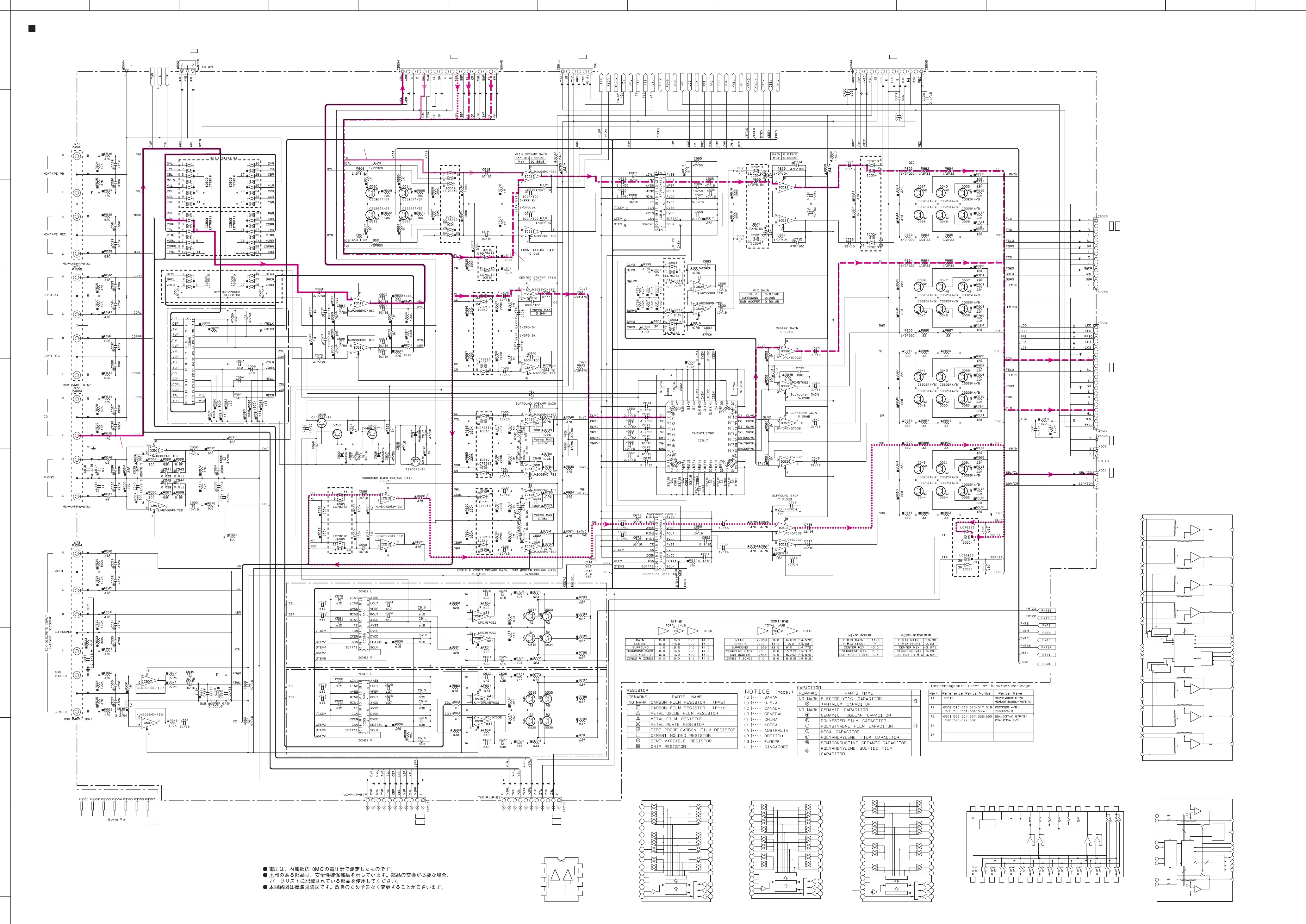
RX-V2400/RX-V2400RDS/DSP-AX2400/RX-V1400/RX-V1400RDS/HTR-5690/DSP-AX1400
SCHEMATIC DIAGRAM (FUNCTION 2/2)
90
★ All voltages are measured with a 10MΩ/V DC electronic volt meter.
★ Components having special characteristics are marked s and must be replaced
with parts having specifications equal to those originally installed.
★ Schematic diagram is subject to change without notice.
Page 91
to OPERATION (3)
I3
Page 88
to DSP
C1 Page 93
to POWER (3)
J8 Page 91
to OPERATION (3)
I5
IC501, 507, 511, 513~515, 518, 524, 525: NJM2068MD
IC521, 523, 527~IC530: µPC4570G2
Dual OP-Amp.
–+
OUT1
–IN1
–VCC
+VCC
OUT2
1
2
3
4
5
+IN1 –IN2
+IN2
– +
6
7
8
IC502, 509: LC78212
Analog Function Switch
1
2
3
4
5
6
7
8
30
29
28
27
26
25
24
23
L1
L2
L3
LCOM1
L4
L5
L6
LCOM2
R1
R2
R3
RCOM1
R4
RCOM2
R5
R6
9
10
11
22
21
20
19
16
12
18
17
14
15
13
LEVEL SHIFTER
LATCH
CONTROL
SHIFT REGISTER
ZZ
ZZ
ZZ
L7
L8
RES
S
V
DD
V
SS
V
EE
LCOM3
RCOM3
R7
R8
D1
CL
CE
IC503: LC78211
Analog Function Switch
1
2
3
4
5
6
7
8
9
10
11
30
29
28
27
26
25
24
23
22
21
20
19
16
12
18
17
14
15
13
LEVEL SHIFTER
LATCH
CONTROL
SHIFT REGISTER
ZZ
ZZ
ZZ
L1
L2
L3
L4
LCOM1
L5
L6
L7
L8
RES
S
V
DD
V
SS
V
EE
LCOM2
LCOM3
R1
R2
R3
R4
RCOM1
RCOM2
RCOM3
R5
R7
R8
D1
CL
CE
R6
IC504, IC510: LC78213
Analog Function Switch
1
2
3
4
5
6
7
8
9
10
11
30
29
28
27
26
25
24
23
22
21
20
19
16
12
18
17
14
15
13
LEVEL SHIFTER
LATCH
CONTROL
SHIFT REGISTER
ZZ
ZZ
ZZ
L1
L2
LCOM1
L3
L4
LCOM2
L5
LCOM3
L7
RES
S
V
DD
V
SS
V
EE
L6
LCOM4
R1
R2
RCOM1
R3
R4
R6
RCOM4
RCOM2
RCOM3
R7
D1
CL
CE
R5
F-SW1
F-SW1: INPUT FUNCTION 1
F-SW2: INPUT FUNCTION 2
*
32 31 30 29 28 27 26 25 24 23 22 21 20 19 18 17
1 2 3 4 5 6 7 8 9 10 11 12 13 14 15 16
IC506: BD3841FS
Function Switch
DGND
F-SW2
CL
DA
VEE
BIAS
VCC
RECA1
RECA2
RECB1
RECB2
RECC1
RECC2
OUT1
OUT2
INI1
INI2
INA1
INA2
INB1
INB2
INC1
INC2
IND1
IND2
INE1
INE2
INF1
INF2
ING1
ING2
INH1
INH2
LOGIC
+
–
+
–
+
–
+
–
12
LIN2
9
LOUT
8
VREF
VREF
VREF
256
256
Reset
Vref
Generator
&
Reset
pulse
Generator
2
SDATAO
20
SDATAI
19
CSN
1
SCLK
16
TE
18
ZCEN
S/P
Register
Control
Register
L
Zero Cross
Detection
IC516, 519, 526, 531: YAC520-EE2
Stereo Digital Volume Controller
11
LIN1
4
DVSS
3
DVDD
13
AVSS
6
AVDD
17
ICN
+
–
R
14
RIN2
7
ROUT
15
RIN1
+
–
16
3
IN1
34
OUT1
OUT2
VolB: 50kohm
VolA: 30kohm
45
TE1
44
TE2
39
ZCEN2
38
ZCEN1
2
AVDD
46
DGND
47
REF
1
AVSS
43
SDATAO (OD)
41
SDATAI
42
SCLK
40
20
19
18
CSN
Control
Register
IC517: YAC523-EVR2
Digital Volume
25
REF1B
24
REF1A
0~95dB
100
0~+31.5dB
+
–
OPA
Zero Crossing
Detector
4
IN2
33
VolB: 50kohm
VolA: 30kohm
23
REF2B
22
REF2A
0~95dB
100
0~+31.5dB
+
–
OPA
Zero Crossing
Detector
Zero Crossing
Detector
5
IN3
32
OUT3
OUT4
VolB: 50kohm
VolA: 30kohm
21
REF3B
20
REF3A
0~95dB
100
0~+31.5dB
+
–
OPA
Zero Crossing
Detector
Zero Crossing
Detector
6
IN4
31
VolB: 50kohm
VolA: 30kohm
19
REF4B
18
REF4A
0~95dB
100
0~+31.5dB
CH1, 2, 3, 4 Control
56
+
–
OPA
Zero Crossing
Detector
Zero Crossing
Detector
S/P
Register
OUT5
14
REF6B
VolB: 50kohm
VolA: 30kohm
8
IN6
13
REF7A
0~95dB
100
0~+31.5dB
+
–
OPA
12
REF7B
OUT6
OUT7
VolB: 50kohm
VolA: 30kohm
9
IN7
15
REF6A
0~95dB
100
0~+31.5dB
+
–
OPA
16
REF5B
VolB: 50kohm
VolA: 30kohm
7
IN5
17
REF5A
0~95dB
100
0~+31.5dB
CH5, 6, 7 Control
+
–
OPA
VOLUME
VOLUME
VOLUME
SELECTOR
ZONE 3 VOLUME
RX-V1400/RX-V1400RDS/HTR-5690/DSP-AX1400
: Page 95
to VIDEO (4)
H7
RX-V2400/RX-V2400RDS/DSP-AX2400
: Page 94 H7
Page 93
to POWER (1)
A4Page 93
to POWER (6)
E2 Page 88
to DSP
B1
RX-V1400/RX-V1400RDS/HTR-5690/DSP-AX1400
: Page 95
to VIDEO (6)
C3
RX-V2400/RX-V2400RDS/DSP-AX2400
: Page 94 C3
RX-V1400/RX-V1400RDS/HTR-5690/DSP-AX1400
: Page 95
to VIDEO (6)
B3
RX-V2400/RX-V2400RDS/DSP-AX2400
: Page 94 B3
0
0
0
0
0
0
0
0
0
0
0
0
0
0
0
0
00
0
0
00
0
0
0
0
0
0
0
0
0
0
0
0
0
0
0
0
0
0
0
0
00
0
0
00
0
0
0
0
0
00
0
0
0.7
0
0
0.7
0
0
0
00
0
0
00
00
00
0
0
11.5
0
00
0
0
0
0
0
0
0
0
0
0
0
0
-11.8
-11.8
0
0
0
0
-11.8
-11.8
0
0
0
0
-11.8
-11.8
0
0
0
0
-11.8
-11.8
0
0
0
0
-11.8
-11.8
0
0
0
0
-11.8
-11.8
0
0
0
0
-11.8
-11.8
0
0
0
0
-11.8
-11.8
0
0
0
0
-11.8
-11.8
0
0
0
0
-11.8
-11.8
0
0
0
0
-11.8
-11.8
0
0
0
0
-11.8
-11.8
0
0
0
0
-11.9
0
00
0
0
0
0
0
0
11.5
0
0
0
-11.9
0
00
00
0
0
11.5
0
0
0
-11.9
0
0.1
0.1
11.5
0.1
0
0
0
0
0
0
0
0
0
-6.0
6.2
0.1
0
0.1
0.1
0
0.1
0.1
2.6
2.6
0
2.6
2.6
0
5.5
0
4.9
0
2.6
2.6
2.6
5.0
0
0
5.0
0.1
4.9
4.9
-6.0
-6.0
-0.9
0
0
0
5.0
4.9
4.9
4.9
6.2
6.2
0
-6.0
0
0
0
0
0
0
0
0
0
0
0
0
0
0
0
0
0
0
-11.9
0
0.1
0.1
11.5
0
0
0
-11.9
0
0
0
11.5
0
0
0
-11.9
0
00
0
00
0
0
0
11.5
0
0
0
-11.9
0
0
0
11.5
0
0
0
-11.9
0
00
0
0
0
0
0
0
11.5
0
0
0
-11.9
0
00
0
0
0
0
0
0
11.5
0
0
0
-11.9
0
00
0
0
0
0
0.1
0.1
11.5
5.0 11.5
4.7
5.6
5.6
0
11.5
6.2
6.8
6.8
0
0
0
0
11.5
-6.0 -12.0
0.2
0.2
0.3
-11.9
0.3
0
0
11.5
0
0
0
-11.9
0
0
0
11.5
0
0
0
-11.9
0
0
0.7
0
0
0.7
2.6
2.6
0
2.6
2.6
0
5.5
0
4.9
0
2.6
2.6
2.6
5.0
0
0
5.0
4.9
4.9
4.9
6.3
5.1
5.7
11.5
-12.0
0
0
0
0
0
0
5.2
0
FRONT L
ANALOG IN L
DIGITAL IN
CENTER
SURROUND BACK L
µPC4570G2
µPC4570G2
2.7K
2.7K
680
680
s32
s17
s7
s9
s9
s10
s8
s8
s10
 Loading...

