A
1
2
3
4
5
6
7
8
9
10
BCDEFGH I JK
L MN
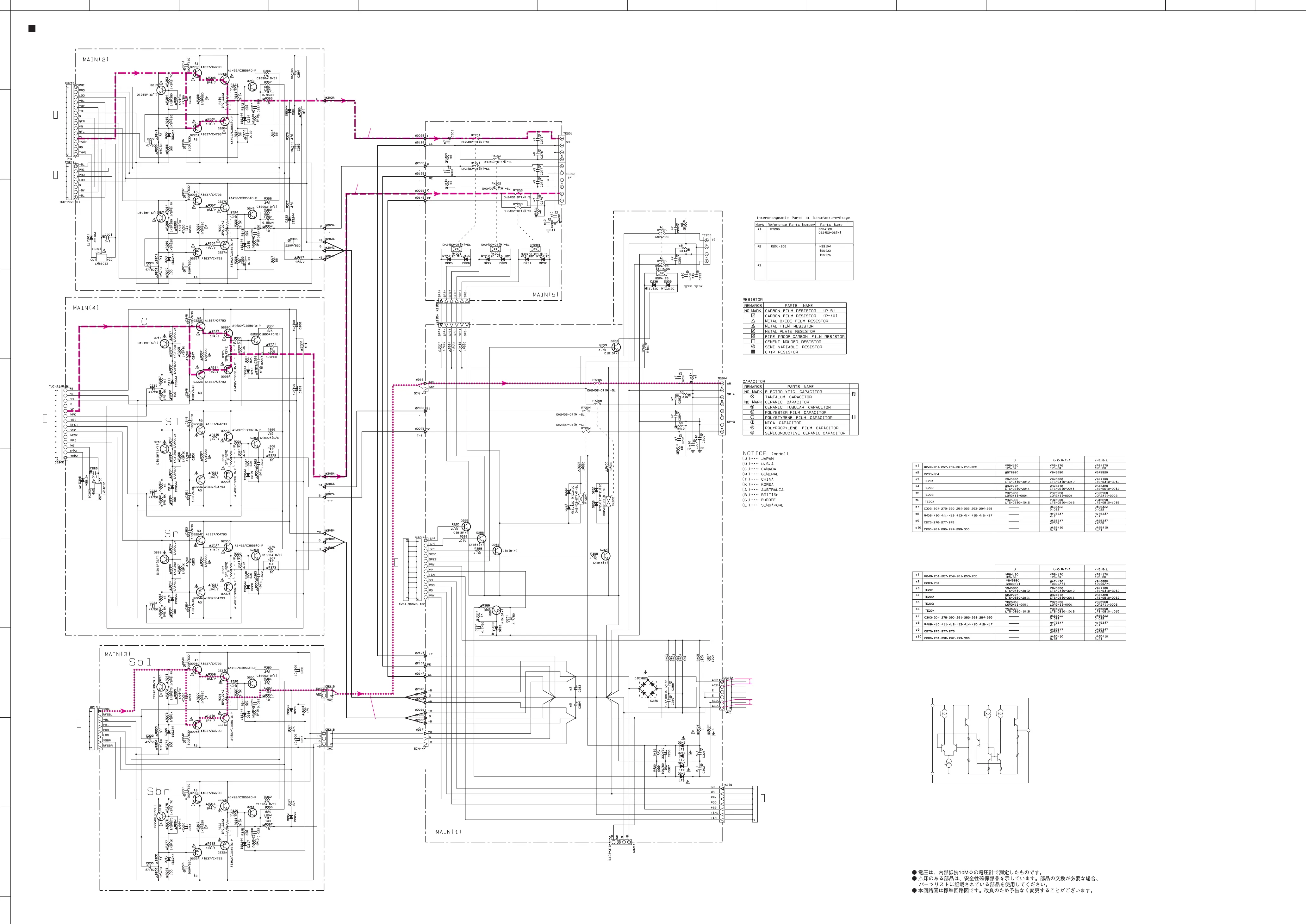
RX-V2400/RX-V2400RDS/DSP-AX2400/RX-V1400/RX-V1400RDS/HTR-5690/DSP-AX1400
SCHEMATIC DIAGRAM (MAIN)
92
★ All voltages are measured with a 10MΩ/V DC electronic volt meter.
★ Components having special characteristics are marked s and must be replaced
with parts having specifications equal to those originally installed.
★ Schematic diagram is subject to change without notice.
IC201, 202: LM61CIZ
Temperature Sensor
Vout
+Vs
GND
2400
x: NOT USED
O: USED / APPLICABLE
1400
x: NOT USED
O: USED / APPLICABLE
FRONT L POWER AMP
FRONT R POWER AMP
CENTER POWER AMP
SURROUND L POWER AMP
SURROUND R POWER AMP
SURROUND BACK L POWER AMP
SURROUND BACK R POWER AMP
Page 93
to POWER (1)
D2
Page 93
to POWER (1)
D5
Page 93
to POWER (6)
G2
Page 93
to POWER (6)
G2
to Power Transformer
Page 89
to FUNCTION
H1
Page 93
to POWER (5)
E6
1.0
1.0
5.2
0
0.8
1.0
1.0
5.2
0
0.8
-1.0
-1.0
-1.0
-57.1
1.0
58.3
58.3
-58.3-58.3
0
0
0
0
0
0
0
58.0
0
0
1.1
-1.0
-1.0
-1.0
-57.1
1.1
58.3
58.3
-58.3
-58.3
-0.5
-0.5
-0.5
-0.5
0.5
0.5
0.5
0
0
0
0
0
0
0
58.0
0
0
1.1
-1.0
-1.0
-1.0
-57.1
1.0
58.3
58.3
-58.3
-58.3
0
0
0
0
0
0
0
58.0
0
0
1.0
-1.0
-1.0
-1.0
-57.1
1.0
58.3
58.3
-58.3
-58.3
-0.5
-0.5
-0.4
-0.4
0.5
0.5
0.5
0.5
0
0
0
0
0
0
0
58.0
0
0
1.0
-1.0
-1.0
-1.0
-57.1
1.0
58.3
58.3
-58.3
-58.3
0
0
0
0
58.0
0
0
0
1.0
-1.0
-1.0
-1.0
-57.1
1.0
58.3
58.3
-58.3
-58.3
-0.5
-0.5
-0.5
-0.5
0.5
0.5
0.5
0.5
0
0
0
0
0
58.0
0
0
1.0
-1.0
-1.0
-1.0
-57.1
1.0
58.3
58.3
-58.3
-58.3
-0.5
-0.5
0.5
0.5
0
0
0
0
0
58.0
0
0
1.0
25.4
12.8
42.9
42.9
43.5
43.5
43.5
0
0
11.0
0.2 0.243.5
23.043.5
25.7
10.6
0.2
25.7
10.6
0.1
0.1
0.1
0.8
0.8
0.2
-45.0
-33.3
0
0
58.3
43.5
-0.1
-0.1
-0.1
-0.1
43.5
-45.0
-45.0
-58.3
-33.9
0
0.1
0.8
0.2
0
0
43.5
0
AC 67.7
AC 85.7
FRONT L
CENTER
SURROUND BACK L
 Loading...

