HFIG
3 71 2
4
6
58 BA9 0 1
2
3
4
5
6
7
8
9
0
A
B
C
D
E
F
G
H
I
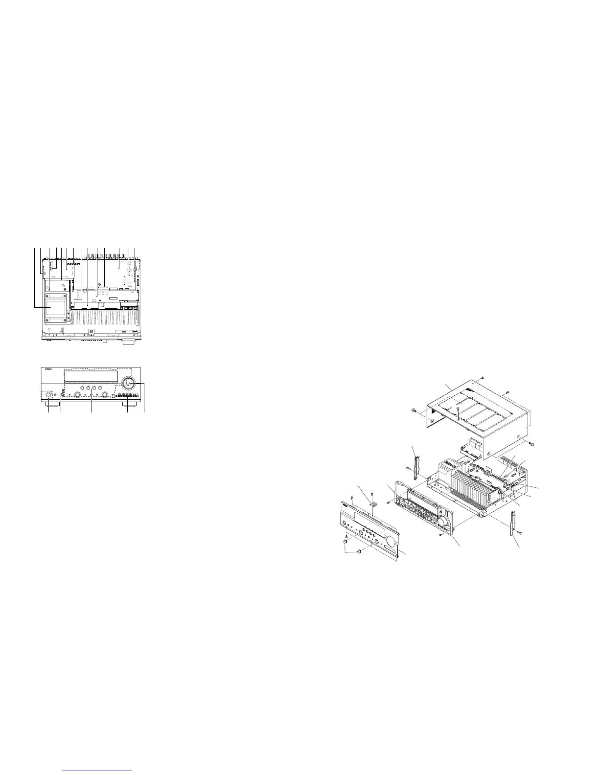
POWER TRANSFORMER
FUNCTION (6) P.C.B.
FUNCTION (3) P.C.B.
FUNCTION (2) P.C.B. (J model)
VIDEO (2) P.C.B.
VIDEO (1) P.C.B.
FUNCTION (4) P.C.B. (R, L models)
MAIN (1) P.C.B.
MAIN (2) P.C.B.
DIGITAL P.C.B.
FUNCTION (9) P.C.B.
FUNCTION (1) P.C.B
Tuner (U, C, R, T, K, A, G, E, F, L, J models)
FUNCTION (5) P.C.B. (B model)
OPERATION (2) P.C.B.
OPERATION (3) P.C.B.
OPERATION (1) P.C.B.
OPERATION (4) P.C.B.
OPERATION (5) P.C.B.
DC
E
■ INTERNAL VIEW
• Top view
• Front view
Fig. 1
(番号順に部品を取り外してください。)
AC電源コンセントから、電源コードを抜いてください。
1. トップカバーの外し方
a.
1
のネジ4本、
2
のネジ5本、
3
のネジ1本を外しま
す。(Fig.1)
b. トップカバーを後方へスライドさせ、取り外します。
(Fig.1)
2. フロントパネルユニットの外し方
a. ノブを2個取り外します。(Fig.1)
b.
4
のネジ1本を外し、サポートトップを取り外しま
す。(Fig.1)
c.
5
のネジ6本を外します。(Fig.1)
d. フロントパネルユニットを取り外します。(Fig.1)
3. サブシャーシユニットの外し方
a.
6
のプッシュリベット2本を外します。(Fig.1)
b. プレートサイドLおよびプレートサイドRを取り外しま
す。(Fig.1)
c.
7
のネジ2本を外します。(Fig.1)
d. CB30、CB46、CB63、CB201、CB221、CB422を外
します。(Fig.1)
e. サブシャーシユニットを取り外します。(Fig.1)
(Remove parts in the order as numbered.)
Disconnect the power cable from the AC outlet.
1. Removal of Top Cover
a. Remove 4 screws (1), 5 screws (2) and screw (3).
(Fig. 1)
b. Slide the top cover rearward to remove it. (Fig. 1)
2. Removal of Front Panel Unit
a. Remove 2 knobs. (Fig. 1)
b. Remove screw (4) and then remove the support top.
(Fig. 1)
c. Remove 6 screws (5). (Fig. 1)
d. Remove the front panel unit. (Fig. 1)
3. Removal of Sub Chassis Unit
a. Remove 2 push rivets (6). (Fig. 1)
b. Remove the plate side L and plate side R. (Fig. 1)
c. Remove 2 screws (7). (Fig. 1)
d. Remove CB30, CB46, CB63, CB201, CB221 and
CB422. (Fig. 1)
e. Remove the sub chassis unit. (Fig. 1)
■ DISASSEMBLY PROCEDURES/分解手順

 Loading...
