To POWER SUPPLY UNIT
To CB5 of OPERATION (2)
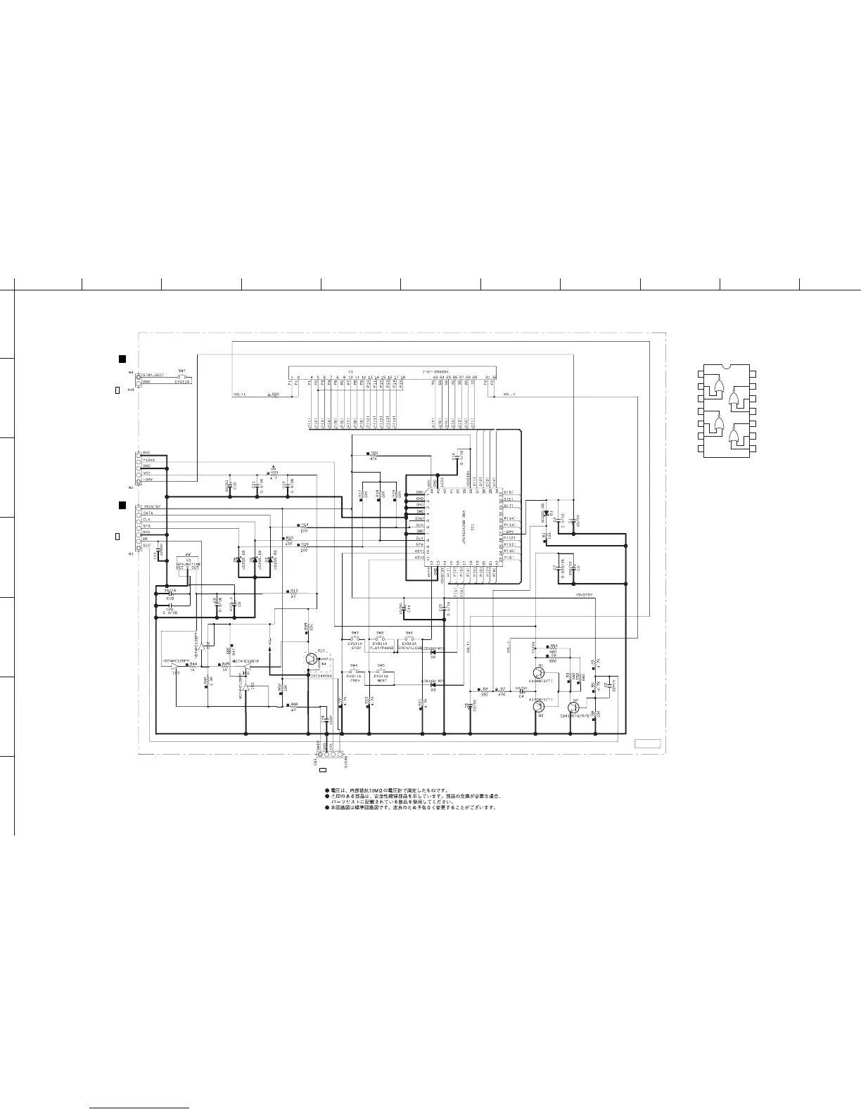
★ All voltages are measured with a 10MΩ/V DC electronic volt meter.
★ Components having special characteristics are marked s and must be replaced
with parts having specifications equal to those originally installed.
★ Schematic diagram is subject to change without notice.
IC2 : HD74HC126FP
Quadruple Bus Buffer Gates
(with 3-state outputs)
1
2
3
4
5
6
7
14
13
12
11
10
9
8
1C
1A
1Y
2C
2A
2Y
GND
Vcc
4C
4A
4Y
3C
3A
3Y
STANDBY/ON
FTD DISPLAY
µPROCESSOR
TACT SWITCH
+5STBY
Page 29 A1 Page 29 B1
Page 35 D5
1P 22
■ SCHEMATIC DIAGRAM (OPERATION 1/2)