6F65G11
8-10
9
8
7
6
5
4
3
2
1
Wring diagram/Ignition and ignition control system
Ignition and ignition control sys-
tem
Checking the ignition spark gap
1. Disconnect the spark plug caps from the
spark plugs.
2. Connect a spark plug cap to the special
service tool.
3. Crank the engine and observe the spark
through the discharge window of the
spark gap tester. Check the ignition sys-
tem if the spark is weak.
w
9 Do not touch any of the connections of
the spark gap tester leads.
9 Do not let sparks leak out of the
removed spark plug caps.
9 Keep flammable gas or liquids away,
since this test can produce sparks.
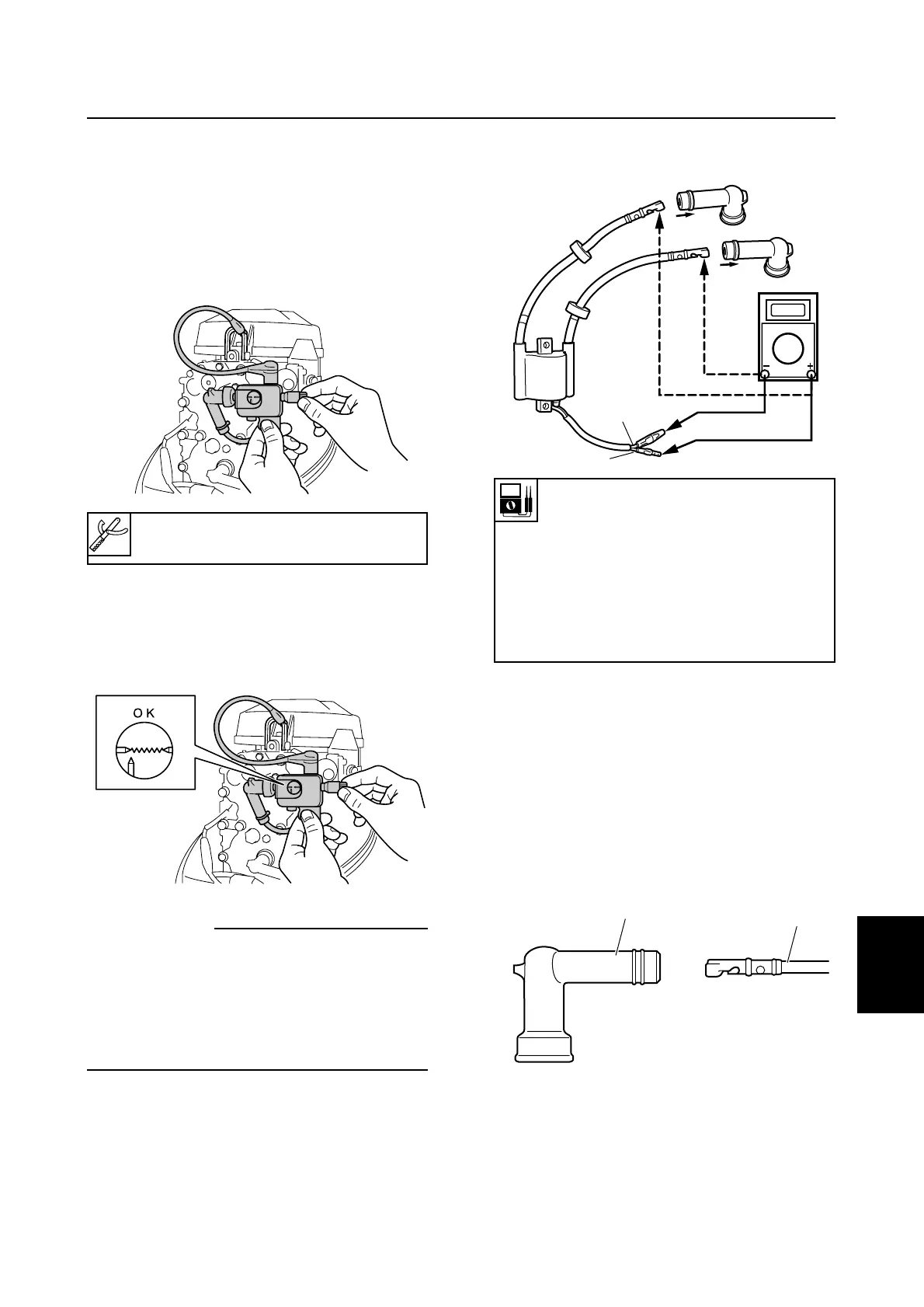
Checking the ignition coil
1. Remove the spark plug cap from the
spark plug.
2. Disconnect the ignition coil connector.
3. Measure the ignition coil resistance.
Replace if out of specification.
Checking the spark plug caps
1. Check the spark plug caps for cracks or
damage. Replace if necessary.
2. Remove the spark plug cap 1 from the
spark plug wire 2.
3. Check the spark plug wire for damage or
cracks. Replace if necessary.
Ignition tester: 90890-06754
Ignition coil resistance:
å
Primary coil:
Orange (O) — Black (B)
0.26 — 0.35Ω at 20°C (68°F)
∫
Secondary coil:
Spark plug wire —
Spark plug wire
6.8 — 10.2 kΩ at 20°C (68°F)

 Loading...