ELEC
8-13
6F65G11
Electrical systems
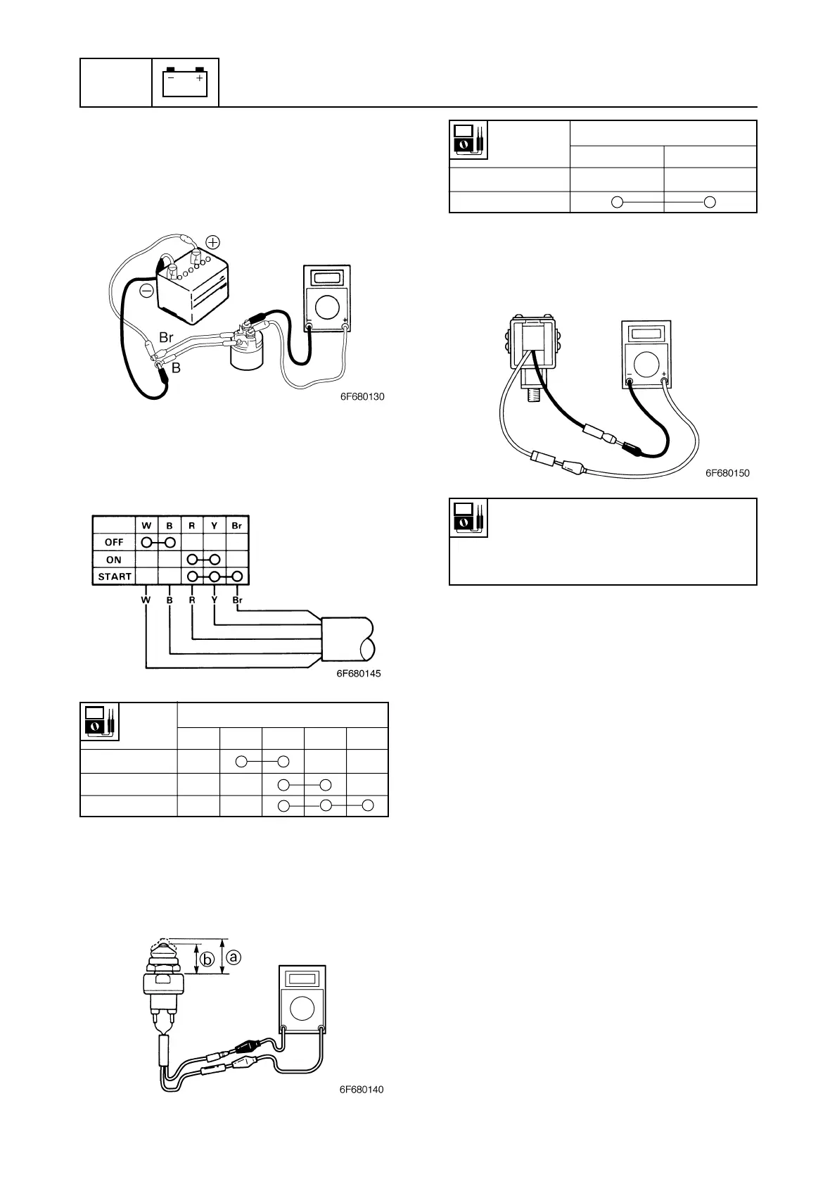
Checking the choke solenoid (W)
1. Measure the resistance of the choke
solenoid.
5. Check that there is no continuity between
the starter relay terminals after discon-
necting a battery terminal from the brown
or black lead. Replace if there is continu-
ity.
Checking the engine start switch
(WH)
1. Check the engine start button for conti-
nuity. Replace if there is no continuity.
Checking the neutral switch (WH, W:
if equipped)
1. Check the neutral switch for continuity.
Replace if there is no continuity.
Switch
Lead color
position
White (W) Black (B) Red (R) Yellow (Y) Brown (Br)
OFF
ON
START
Switch Lead color
position Brown (Br) Brown (Br)
Free a
Push b
Choke solenoid resistance
(reference data):
Blue (L) — Black (B)
3.6 — 4.4 Ω at 20°C (68°F)

 Loading...