HS80M/HS50M
9
HS80M
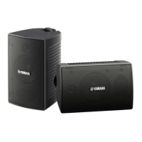
5. INPUT Circuit Board
(Time required: about 3 minutes)
5-1 Remove the rear panel assembly. (See procedure 3.)
5-2 Remove the four (4) screws marked [110] and the
screw marked [115]. (Fig. 3)
5-3 Remove the LEVEL knob, the hexagonal nut [E] and
washer [D]. (Fig. 3, Photo. 5)
5-4 Remove the hexagonal nut [F] on the phone type in-
put connector. The INPUT assembly can then be re-
moved. (Photo. 5)
5-5 Remove the three (3) screws marked [G] and remove
the case PWB. (Photo. 3)
The Input circuit board can then be removed.
* The case PWB is not a component of the INPUT cir-
cuit board. When replacing the INPUT circuit board,
remove the case PWB and reuse it.
5. INPUTシート(所要時間:約3分)
5-1 リアパネルAssyを外します。(3項参照)
5-2 [110]のネジ4本と[115]のネジ1本を外します。
(図3)
5-3 LEVELつまみと[E]の六角ナットおよび[D]のワッ
シャを外します。(図3、写真5)
5-4 フォーンタイプ入力端子の六角ナット[F]を外し、
INPUTAssyを外します。(写真5)
5-5 [G]のネジを3本外してケースPWBを外し、INPUT
シートを取り出します。(写真3)
* ケースPWBはINPUTシートの構成部品ではありませ
ん。シート交換時には、取外して使用してくださ
い。
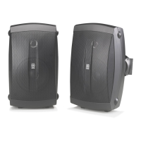
4-3 IC801とIC802のパターン側のハンダ(22カ所)を外し
ます。(写真1)
4-4 [A]のネジ2本を外し、放熱板(IC801、IC802付)を外
します。(写真1)
[B]のネジ2本を外し、IC801とIC802を外します。
(写真1)
4-5 [C]のネジ4本を外し、AMP取付金具を外してAMP
シートを取り出します。(写真1)
[A]
[C]
[C]
[B]
IC801
IC802
AMP mounting BRACKET
(AMP取付金具)
AMP mounting BRACKET
(AMP取付金具)
AMP mounting BRACKET
(AMP取付金具)
AMP mounting BRACKET
(AMP取付金具)
AMP circuit board
(AMPシート)
AMP circuit board
(AMPシート)
SPACER
(スペーサー)
HEAT SINK
(放熱板)
INPUT Circuit Board
(INPUTシート)
INPUT Circuit Board
(INPUTシート)
CASE PWB
(ケースPWB)
CASE PWB
(ケースPWB)
Photo. 1(写真1)
<AMP Unit>
<AMPユニット>
Photo. 2(写真2)
<INPUT Assembly>
<InputAssy>
4-3 Unsolder soldered parts (22 locations) on the pat-
tern side of IC801 and IC802. (Photo. 1)
4-4 Remove the two (2) screws marked [A] and remove
the heat sink with IC801 and IC802. (Photo. 1)
Remove the two (2) screws marked [B] and remove
IC801 and IC802. (Photo. 1)
4-5 Remove the four (4) screws marked [C], remove the
AMP mounting bracket. The AMP circuit board can
then be removed. (Photo. 1)
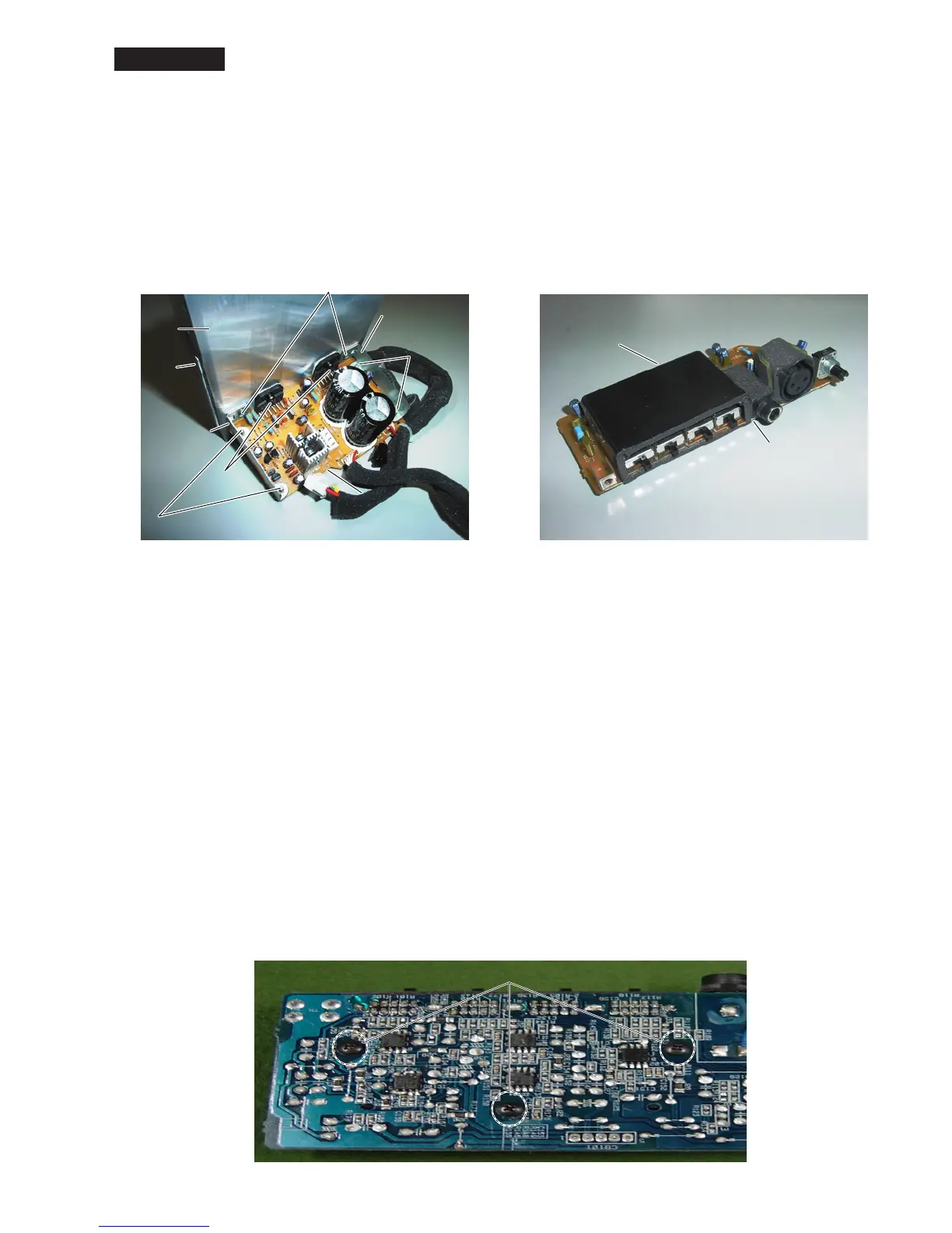
Photo. 3(写真3)
[G]
 Loading...