Do you have a question about the Yamaha HTR-3064 and is the answer not in the manual?
Guidelines for service personnel including component handling, safety, and materials.
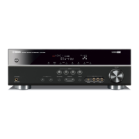
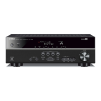
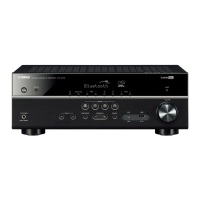
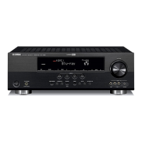
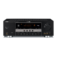
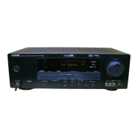
Visual overview of the front panel and its layout for RX-V371 models.
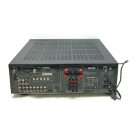
Diagrams of rear panel connections for RX-V371 (U, C), (R, S), and (T) models.
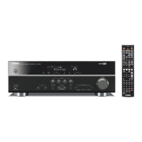
Button layouts for different remote control models: RAV331, RAV332, RAV433.
Detailed specifications for audio output power, input levels, and video signal characteristics.
Specifications for FM/AM tuners, volume control, and tone control features.
General specifications including power, dimensions, weight, finish, and accessories.
Diagram showing the internal layout and identification of major components.
Crucial safety measures to follow during servicing to prevent injury or damage.
Step-by-step guide for removing the top cover and front panel unit.
Instructions for removing the DIGITAL and OPERATION (4) P.C.B.s.
Comprehensive guide to updating firmware, including confirmation, tools, connection, and procedures.
Overview of the self-diagnostic menu structure and key functional categories.
Procedures for entering, exiting, and special modes of the self-diagnostic function.
Explanations for protection function triggers and their causes.
Diagrams detailing pin connections and grid assignments for display segments.
Table specifying anode connections for various display elements.
Pinout and function description for IC21 on the main PCB.
Overall block diagram illustrating the unit's system architecture and signal flow.
Layout diagrams for DIGITAL, MAIN (1), and AM/FM Tuner printed circuit boards.
Visual representations of pin connections for integrated circuits, diodes, and transistors.
Circuit diagrams for the digital section of the unit (Part 1/4).
Circuit diagrams for the operation sections of the unit (Part 1/2).
Circuit diagrams for the main sections of the unit (Part 1/3).
List of electrical component parts with abbreviations and warnings.
List of replacement parts for digital and operation sections.
Replacement parts for main sections and detailed resistor specifications.
Exploded view diagram showing the overall assembly of unit parts.
List referencing part numbers to their descriptions, markets, and remarks.
Diagrams showing the button layouts for RAV331, RAV332, and RAV433 remotes.
Circuit diagrams for the RAV331 and RAV332 remote controls.
Key code mappings for input selection and tuner functions.
Key code mappings for DSP modes, Scene selection, and menu navigation.
Key code mappings for TV functions, volume, source, and numeric keys.
Instructions on how to enter and navigate the Advanced Setup menu.
Procedures for setting speaker impedance and managing remote control signals.
Procedures for initializing unit settings and adjusting FM/AM frequency steps.
| Channels | 5.1 |
|---|---|
| HDMI Inputs | 4 |
| HDMI Outputs | 1 |
| Dolby Technologies | Dolby TrueHD, Dolby Digital Plus, Dolby Digital |
| YPAO Sound Optimization | Yes |
| Tuner | AM/FM |
| Bluetooth | No |
| USB Port | No |
| Video Upconversion | No |
| Dimensions (W x H x D) | 435 x 151 x 315 mm |
| Weight | 7.5 kg |
| DTS Technologies | DTS |
| Connectivity | HDMI |