Do you have a question about the Yamaha HTR-3063 and is the answer not in the manual?
Identifies and explains critical components requiring specific replacement parts.
Procedure for verifying insulation after service, specific to 120V models.
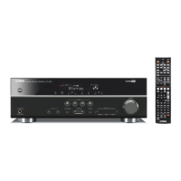
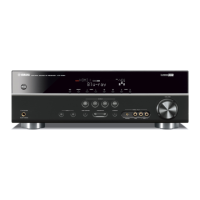
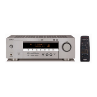
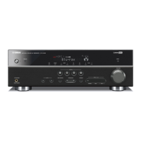
Illustrates front panel configurations for different RX-V367 model variations.
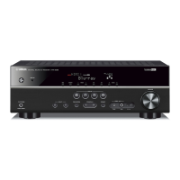
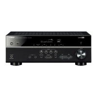
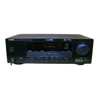
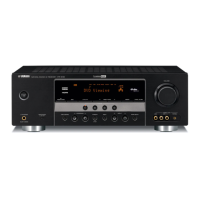
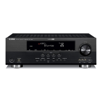
Illustrates front panel configurations for different HTR-3063 model variations.
Details rear panel layouts for U, C, and R model RX-V367 units.
Details rear panel layouts for C, R, and T model HTR-3063 units.
Shows layouts for RAV331, RAV332, and RAV333 remote controls.
Details output power, sensitivity, distortion, and frequency response of the audio section.
Outlines specifications for video signal levels and signal-to-noise ratio.
Lists tuning range, sensitivity, and distortion for FM reception.
Lists tuning range for AM reception.
Covers power supply, consumption, dimensions, weight, and finishes.
Details steps to remove the unit's top cover.
Details steps to remove the front panel assembly.
Instructions for removing the main digital circuit board.
Instructions for removing a specific operation circuit board.
How to check firmware version and checksum before and after updates.
Steps to initialize the EEPROM after firmware updates for proper memory operation.
Lists necessary equipment for performing firmware updates.
Analyzes analog audio signal output in DIRECT mode for diagnostic purposes.
Tests memory margin or full bit output for audio signal diagnostics.
Selects and outputs audio signals input via HDMI for diagnostic checks.
Configures analog switch settings for speaker output in diagnostic mode.
Displays the history of protection function activations for troubleshooting.
Allows writing model name and destination to the back-up IC.
Reserves or inhibits initialization of the back-up IC for user settings.
Displays firmware version, checksums, model name, and destination.
Details pin assignments for the Operation P.C.B. connector.
Shows the layout and assignment of display grid segments.
Provides anode connection mapping for display segments across different groups.
Describes the function of the 8-channel electronic volume IC.
Shows the physical layout of the digital circuit board (Side A and B).
Displays layouts for Operation circuit boards (1 through 9, Side A and B).
Illustrates the physical layout of the main circuit boards (1 through 4, Side A and B).
Diagrams showing pin configurations for various integrated circuits.
Pin connection diagrams for different types of diodes.
Pin connection diagrams for various transistors.
Illustrates the electronic circuits for the digital section.
Shows the electronic circuits for the operation sections.
Displays the electronic circuits for the main sections.
Lists replacement parts specifically for the digital circuit board.
Lists replacement parts for the operation circuit boards.
Lists replacement parts for the main circuit boards.
Diagrams showing the layout of the RAV331, RAV332, and RAV333 remote controls.
Circuit schematics for the RAV331 and RAV332 remote controls.
Setup procedures specific to U and C model units.
Setup procedures specific to R, T, K, A, B, G, F, L model units.
| Channels | 5.1 |
|---|---|
| HDMI Inputs | 4 |
| HDMI Outputs | 1 |
| Dolby Digital | Yes |
| DTS | Yes |
| YPAO | Yes |
| Bluetooth | No |
| USB Port | No |
| Network Connectivity | No |
| Dimensions | 435 x 151 x 315 mm |
| Weight | 7.5 kg |
| Audio Decoding | Dolby Digital, DTS |
| Supported Audio Formats | MP3, WMA |