Do you have a question about the Yamaha HTR-3069 and is the answer not in the manual?
Information about critical components requiring specific replacement parts to maintain specifications.
Procedure to verify insulation and measure leakage current for 120V models after service completion.
Detailed electrical specifications for the audio performance, including output power, frequency response, and tone control.
Essential safety precautions for servicing, including handling high voltages and discharging capacitors.
Step-by-step instructions for removing the top cover of the unit.
Step-by-step instructions for removing the front panel unit.
Instructions for removing the DIGITAL P.C.B., detailing connector and screw removal.
Instructions for removing the MAIN (2) and MAIN (3) P.C.B.s, noting board-to-board connectors.
Method to verify firmware version and checksum using the self-diagnostic function menu.
Procedure to initialize the backup IC (EEPROM) after firmware update to store settings properly.
Monitors power supply voltages, protection status, and limiter controls.
Electrical schematics for the digital section of the receiver, covering multiple pages.
List of individual electrical components like capacitors, resistors, diodes, and ICs available for replacement.
Detailed instructions for updating firmware using a CD, including requirements and steps to create the CD.
Detailed instructions for updating firmware using a USB thumb drive, including preparation and requirements.
Steps to diagnose and resolve issues preventing the firmware update from beginning.
Procedures to follow when an error message appears during the update process.
Methods to recover the receiver if it fails to power on after a firmware update.
Troubleshooting steps specific to USB firmware updates, including drive recognition and error messages.
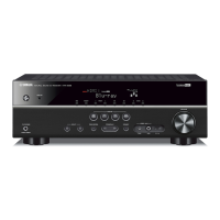
| Receiver type | Surround |
|---|---|
| Audio output channels | 5.1 channels |
| Total Harmonic Distortion (THD) | 0.09 % |
| Power output per channel (1KHz@6 Ohm) | 100 W |
| Power output per channel (20-20KHz@8 Ohm) | - W |
| Bluetooth | Yes |
| AirPlay | - |
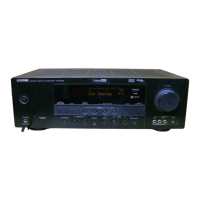
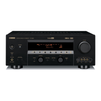
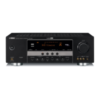
| Display | LCD |
| Product color | Black |
| Audio decoders | DTS-HD Master Audio, Dolby TrueHD |
| Apple docking compatibility | Not supported |
| On Screen Display (OSD) languages | CHI (TR), DEU, ENG, ESP, FRE, ITA, JPN, RUS |
| Power consumption (standby) | 0.3 W |
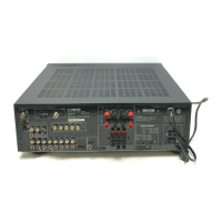
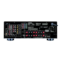
| HDMI in | 4 |
| Audio (L/R) in | 3 |
| USB ports quantity | 1 |
| Digital audio coaxial in | 2 |
| Supported radio bands | AM, FM |
| Optical drive included | No |
| Depth | 315 mm |
|---|---|
| Width | 435 mm |
| Height | 151 mm |
| Weight | 7400 g |