★ All voltages are measured with a 10MΩ/V DC electronic voltmeter.
★ Components having special characteristics are marked
⚠
and must be replaced
with parts having specifications equal to those originally installed.
★ Schematic diagram is subject to change without notice.
●電圧は、内部抵抗 10MΩの電圧計で測定したものです。
●⚠印のある部品は、安全性確保部品を示しています。部品の交換が必要な場合、
パーツリストに記載されている部品を使用してください。
●本回路図は標準回路図です。改良のため予告なく変更することがございます。
A
1
2
3
4
5
6
7
8
9
10
BCDEFGH I JK
L MN
41
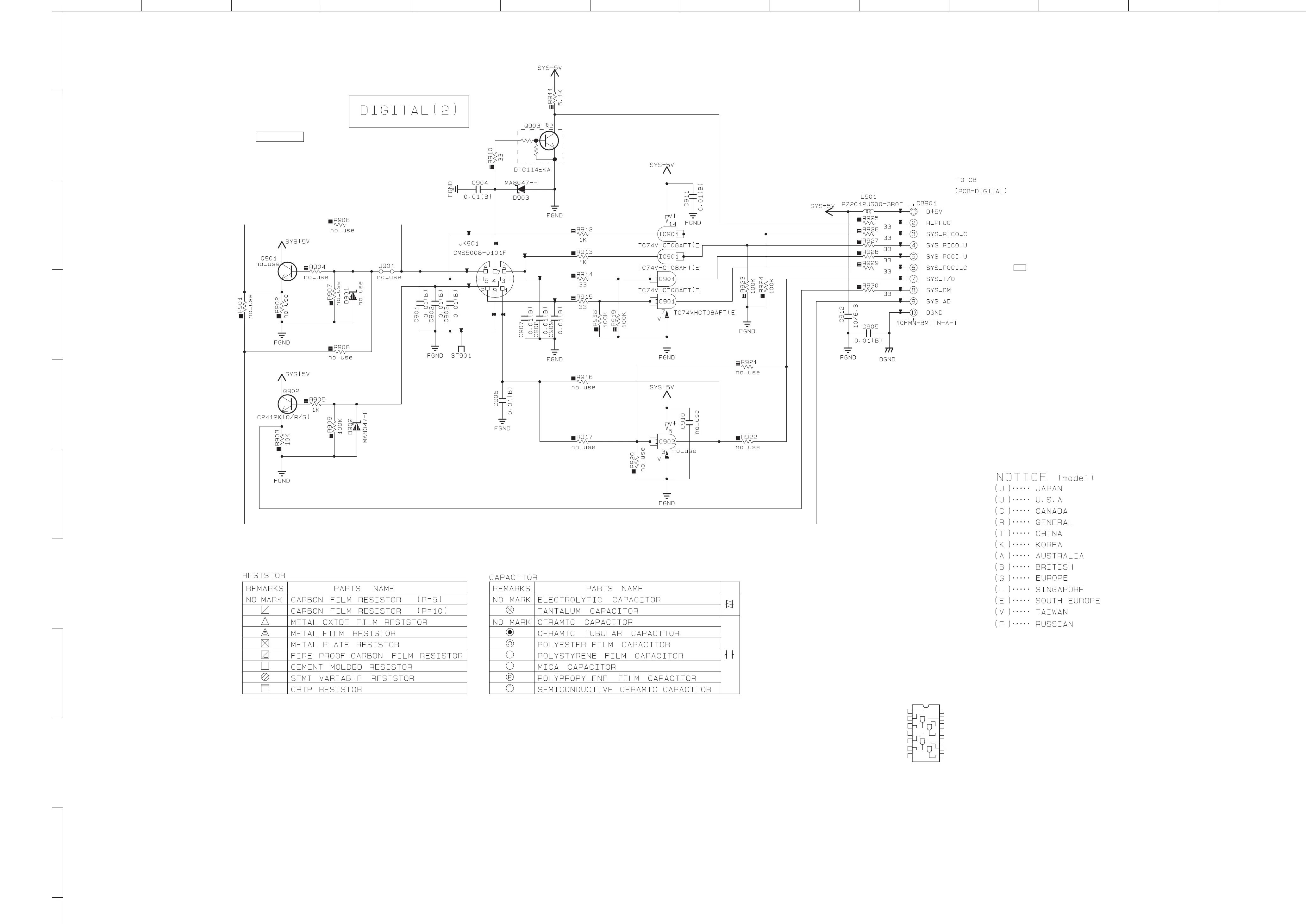
DIGITAL 3/3
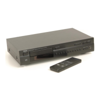
CD-1330
IC901
JK901
CB901
IC901
IC901
IC901
0
0
0
0
0
4.9
2.8
3.5
2.8
4.9
0
3.5
2.8
0
5.0
0
3.4
4.9
IC901: TC74VHCT08AFT
Quad 2-input AND gate
Vcc14
4B
4A
4Y
3B
3A
3Y
1A 1
2
3
13
12
11
10
9
8
4
5
6
7
1B
1Y
2A
2B
2Y
GND
to DIGITAL (1)_CB801
Page 40
G1
DIGITAL (2)
SYSTEM
CONNECTOR
 Loading...