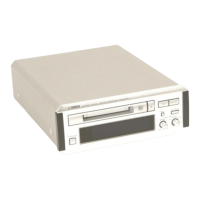
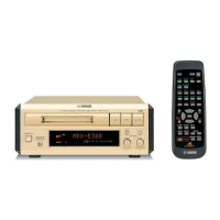
MDX-596
MDX-596
■ DISASSEMBLY PROCEDURES
(Remove parts in disassembly order as numbered.)
Fig. 2
4
■ INTERNAL VIEW
1. Removal of Top Cover
a. Remove 4 screws ( q ) and 3 screw
( w
)
in Fig. 1.
2. Removal of Front Panel
a. Remove 4 connectors.
CB5, CB6, CB7, CB401
b. Remove 3 screws
( e )
in Fig. 1
.
* Arrow marks ( ) are printed to identify the screws to be
removed.
c. Remove 2 screws
( r )
in Fig. 1
.
3. Removal of MD Recorder Unit
a. Remove 1 connector.
CB1
b. Remove 4 screws ( t ) in Fig. 1.
c. Remove 4 screws ( y ) in Fig. 2.
q w
e r t
CB7
CB6
CB1
CB401
CB5
q POWER TRANSFORMER
w MAIN (1) P.C.B.
e POWER SWITCH
r MD RECORDER UNIT
t MAIN (2) P.C.B.
Fig. 1
q
q
Top Cover
w
MD Recorder Unit
Front Panel
r
e
r
t
MD Recorder Unit
t
y
y
Support (Mechanism)
 Loading...