Do you have a question about the Yamaha MG12/4FX and is the answer not in the manual?
| Brand | Yamaha |
|---|---|
| Model | MG12/4FX |
| Category | Music Mixer |
| Language | English |
General safety and handling instructions for product servicing.
Warning about hazardous chemicals in components and safe handling.
Specific instructions for connecting to UK power supply.
Details technical electrical specifications of the mixer.
Lists overall technical characteristics of the mixer.
Details input parameters for various connectors.
Details output parameters for various connectors.
Visual representation of the unit's size and measurements.
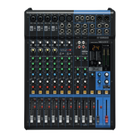
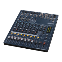
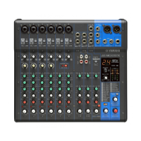
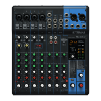
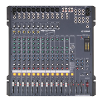
Explains the function of each control element on the console panel.
Explains the rear panel connectors and their functions.
Details pin assignments and signal polarities for various connectors.
Visual layout of the DSP circuit board.
Visual layout of the Power Supply circuit board.
Visual layout of the JACK circuit board.
Visual layout of the MAIN circuit board.
Steps to remove rack mount angles from the unit.
Steps to remove the bottom cover of the unit.
Steps to remove side covers and the power supply board.
Steps to remove the DSP circuit board.
Steps to remove the power switch and AC connector.
Steps to remove the JACK and MAIN circuit boards.
Details the function of each pin on the LSI (CPU).
Block diagram for the AK5381VT A/D converter IC.
Block diagram for the PCM1742KEG D/A converter IC.
Illustrates jumper wire bending and connector insertion procedures.
Defines inspection criteria and power source specifications.
Lists initial settings for controls before inspection.
Specifies initial settings for channel and stereo inputs.
Procedures for verifying indicators and gain level measurements.
Methods for testing frequency response and high-pass filters.
Procedures for testing channel equalization and crosstalk.
Methods for testing peak LEDs and distortion factor.
Procedures for testing maximum output and noise levels.
Details on remaining inspection items.
Final checks before product delivery.
Lists included accessories like AC adapters.
Introduces major categories of electronic components.
Layouts for DSP, PS, JACK, MAIN.
Lists integrated circuits used.
Lists various capacitor types.
Lists various resistor values.
Lists various connector, diode, transistor, and switch types.
Lists rotary and slide variable resistors.
Lists fuses, filters, heat sinks.
Overall system block diagram.
Introduces detailed schematics for different sections.
Detailed circuit diagram for the DSP section.
Detailed circuit diagram for the JACK section.
Detailed circuit diagram for the MAIN section.
Continuation of MAIN section schematic.
Continuation of MAIN section schematic.
Continuation of MAIN section schematic.
Continuation of MAIN section schematic.
Continuation of MAIN section schematic.
Detailed circuit diagram for the Power Supply section.