2. JK Circuit Board
(Time required: About 3 minutes)
2-1 Remove the upper case assembly. (See procedure 1.)
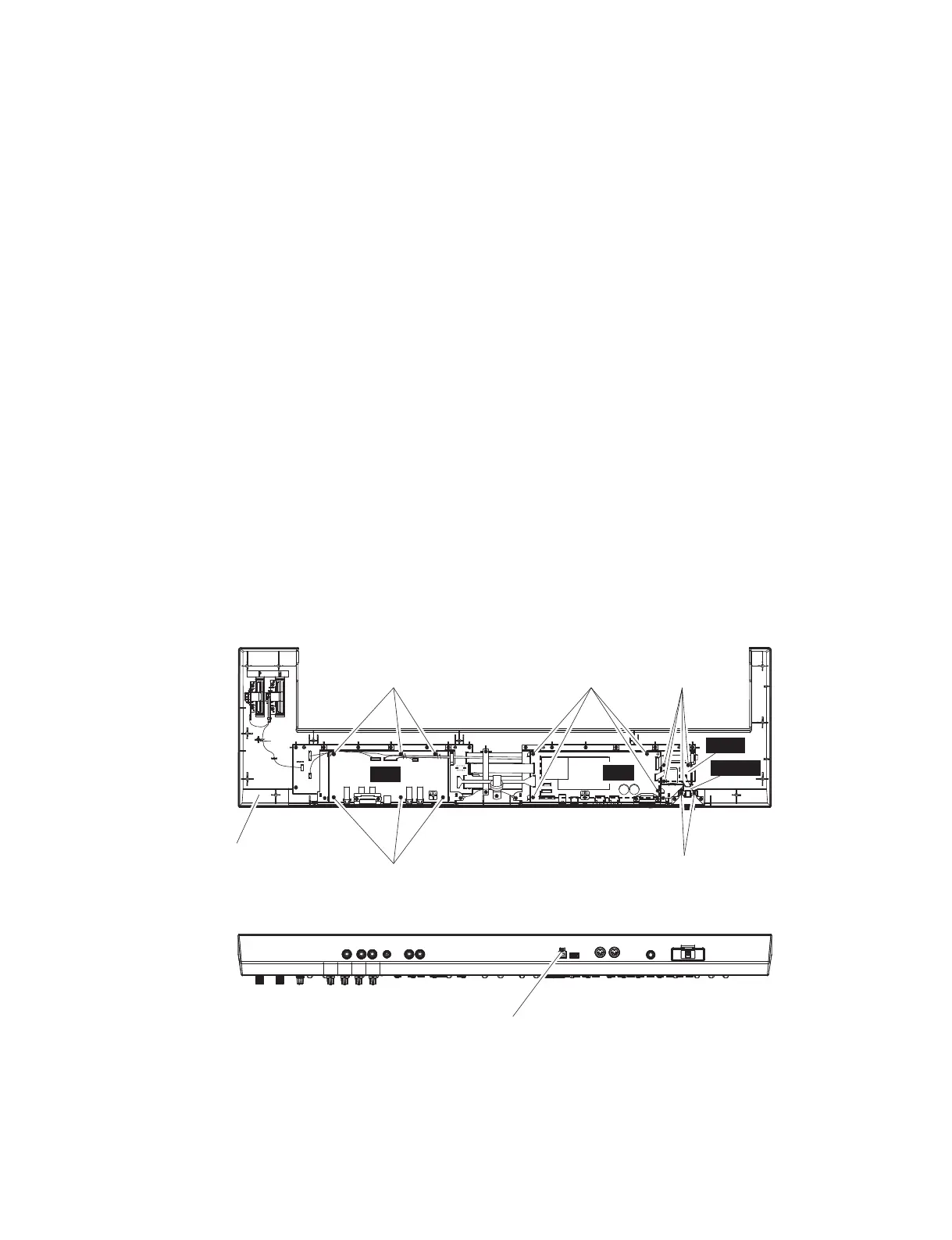
2-2 Remove the six (6) screws marked [U220A]. The JK
circuit board can then be removed. (Fig. 2)
3. DM Circuit Board
(Time required: About 3 minutes)
3-1 Remove the upper case assembly. (See procedure 1.)
3-2 Remove the four (4) screws marked [U220B] and the
screw marked [D30]. The DM circuit board can then
be removed. (Fig. 2)
4. FLT Circuit Board
(Time required: About 3 minutes)
4-1 Remove the upper case assembly. (See procedure 1.)
4-2 Remove the four (4) screws marked [U220C]. The FLT
circuit board can then be removed. (Fig. 2)
5. DC-IN Circuit Board
(Time required: About 3 minutes)
5-1 Remove the upper case assembly. (See procedure 1.)
5-2 Remove the two (2) screws marked [U220D]. The DC-
IN circuit board can then be removed. (Fig. 2)
2. JK シート
(所要時間:約 3 分)
2-1 上ケース Ass'y を外します。(1 項参照)
2-2 [U220A]のネジ 6 本を外し、JK シートを外します。
(図 2)
3. DM シート
(所要時間:約 3 分)
3-1 上ケース Ass'y を外します。(1 項参照)
3-2 [U220B]のネジ 4 本と[D30]のネジ 1 本を外し、
DM シートを外します。(図 2)
4. FLT シート
(所要時間:約 3 分)
4-1 上ケース Ass'y を外します。(1 項参照)
4-2 [U220C]のネジ 4 本を外し、FLT シートを外します。
(図 2)
5. DC-IN シート
(所要時間:約 3 分)
5-1 上ケース Ass'y を外します。(1 項参照)
5-2 [U220D]のネジ 2 本を外し、DC-IN シートを外しま
す。(図 2)
Fig. 2
(図 2)
[U220A] [U220B]
[U220A]
[D30]
DC-IN
FLT
DM
JK
[U220C]
[U220D]
<Bottom view (底面図)>
<Rear view (背面図)>
Upper case assembly
(上ケース Ass'y)
9
MX61/MX49