2
ABCDEFGH I J
1
3
4
5
7
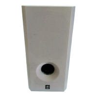
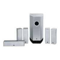
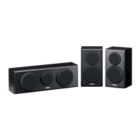
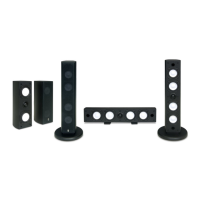
NS-P440/NS-P446
6
10
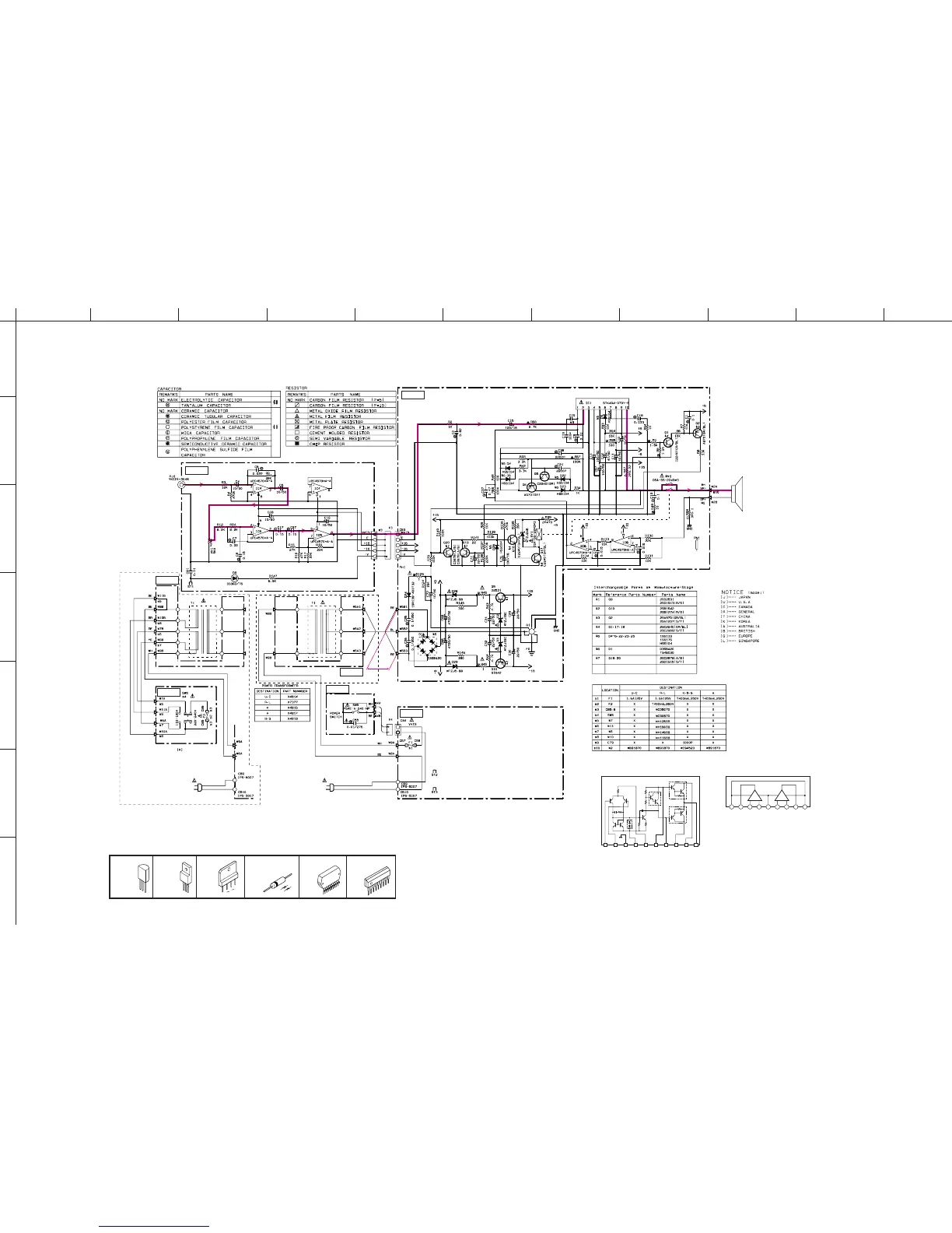
■ SCHEMATIC DIAGRAM
★ All voltages are measured with a 10MΩV DC electronic volt meter.
★ Components having special characteristics are marked s and must be replaced
with parts having specifications equal to those originally installed.
★ Schematic diagram is subject to change without notice.
IC1: STK404-070Y60W
AF Power Amp
13245678910
R1
R4
R5
C1
C2
D1
TR3
TR5
R3
R6
TR4
SUB
R2
TR1
TR2
TR6
TR7
TR8
1
10
STK404-070Y60W
1
9
PIN CONNECTION DIAGRAM OF TRANSISTORS, DIODES AND ICS.
2SB1642
2SD2531
1SR139,400
1SS133,176
MTZJ15C
MTZJ24B
MTZJ5.6B
2SA970
2SC2240
2SC2878
µPC4570HA-A
Anode
Cathode
E
C
B
B
C
E
D3SBA20
IC4~6: µPC4570HA-A
Dual OP-Amp
Vcc Vo
1
-Vm
1
+Vm
1
V
EE
+Vm
2
-Vm
2
Vo
2
Vcc
1234 567 89
++--
12
+
–
0
0
0
0
0
0
0
-1.9
0
0
0
0
0
0
14.5
14.5
-14.6
-14.6
0.2
0.2
0
-34.9
14.5
1.11.7
-35.2
35.1
35.0
35.0
-8.1
35.1
0
0
0
-14.5
23.6
0.8
0.7
1.3
0.2 0.2
0.2
0.2
0
0.2
0.2
0
00
00
0.2 0.2
1.3
0.1
1.3
-30.7
35.0
29.4 29.4
14.5
-29.5
-29.6
-35.2
AC 52.0
-14.5
15
-15.1
1.3
0
0
-8.0
0
0
0
0.7
0
14.5
0
0
0
0
0
0
-1.1
L.P.F.
L.P.F.
DRIVER
R, L models
U, C, K, A, B, G, L models
MAIN (1)
MAIN (3)
MAIN (10)
MAIN (7)
MAIN (5)
MAIN (2)
MAIN (9)
VOLUME
H.P.F.
POWER AMP
A.N.I.C.
LIMITER
PROTECTION
POWER
SUPPLY
REGULATOR
POWER
INPUT