Do you have a question about the Yamaha P-2200 and is the answer not in the manual?
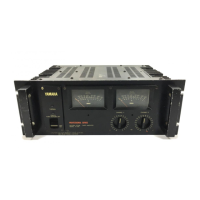
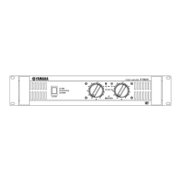
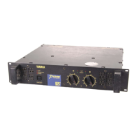
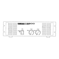
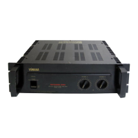
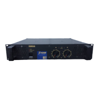
Overview of the P-2200's front panel controls and indicators.
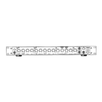
Rear panel connections and indicators for the General, U.K., & Austrian model.
Rear panel details for the U.S. model amplifier.
Rear panel details for the Canadian model amplifier.
Rear panel details for the European model amplifier.
Technical specifications for the amplifier's performance parameters.
Power supply ratings, consumption, and fuses for different models.
Specifications related to the peak meter's indication range and error.
Environmental, dimensional, and weight specifications for the unit.
Graph showing the amplifier's frequency response characteristics.
Graph illustrating THD versus frequency for different loads.
Graph showing output power versus frequency at specified THD.
Graph illustrating THD versus output power.
A high-level functional block diagram of the amplifier's signal path.
Detailed explanation of the input and first stage differential amplifier.
Explanation of the predrive stage transistors and their function.
Details on the drive stage transistors and bias circuits.
Explanation of the toroidal transformer and power supply components.
Explanation of the peak meter's integrated circuit and thermal switch.
Step 1 of disassembly: removing the top cover.
Step 2 of disassembly: removing the transistor cover.
Step 3 of disassembly: removing the main radiator.
Step 4 of disassembly: removing the drive P.C. board.
Step 5 of disassembly: removing the shield plate.
Step 6 of disassembly: removing switch and meter frames.
Step 7 of disassembly: removing the bottom cover.
Step 8 of disassembly: removing the handles.
Step 9 of disassembly: removing the meter P.C. board.
Step 10 of disassembly: removing input/output connectors.
Step 11 of disassembly: removing the temperature sensor transistor.
Step 12 of disassembly: removing the power transistor socket.
Step 13 of disassembly: removing AC cord, outlet, and fuse holder.
Step 14 of disassembly: handling the silicon rectifier.
Step 15 of disassembly: removing meter lamp board and lamp.
Step 16 of disassembly: removing the variable resistor.
Step 17 of disassembly: removing the power transformer.
Step 18 of disassembly: removing meter, switch, and LED boards.
Procedures for adjusting the driver circuit board's idling current.
Procedures for zero and OdB adjustment of the meter.
Detailed layout of the drive stage printed circuit board.
General wiring diagram and color code for the amplifier.
Complete circuit schematic of the P-2200 amplifier.
Schematic variations for the power supply based on export region.