A
1
2
3
4
5
6
7
8
9
10
BCDEFGH I J K
L MN
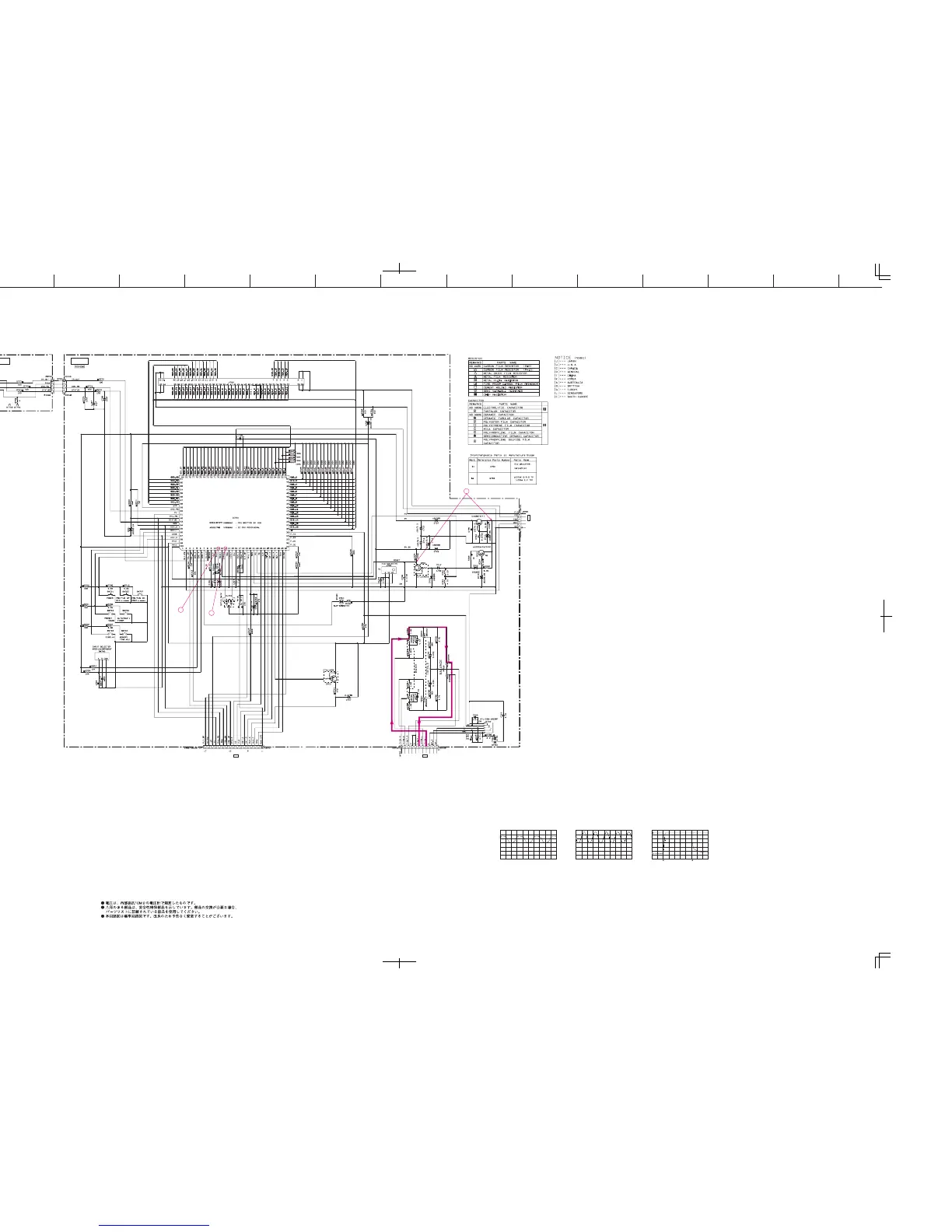
RX-E600/NX-E400
SCHEMATIC DIAGRAM (OPERATION)
22
★ All voltages are measured with a 10MΩ/V DC electronic volt meter.
★ Components having special characteristics are marked s and must be replaced
with parts having specifications equal to those originally installed.
★ Schematic diagram is subject to change without notice.
-28.8
-28.8
-26.6
-24.5
-28.8
-28.8
-26.6
-26.6
-26.6
-24.5
-24.5
-26.7
-26.7
-26.7
-26.7
-26.7
-26.7
-23.9
-23.9
-24.1
-29.1
4.9 5.5
4.8 5.5
5.5
6.1
11.9
6.1
0
11.9
7.3
4.7
0
4.9
4.9
0
0
0
0
6.7
0
11.9
11.2
-28.8
-28.8
-26.7
-26.7
-26.7
-26.7
-26.7
-26.7
-26.7
-26.7
-28.8
-24.5
-26.6
-28.8
-28.8
-28.8
-24.6
-26.6
-28.9
-28.9
-28.9
-24.6
-26.6
-28.9
-28.9
0
-28.9
4.8
-24.6
-26.7
-26.7
-28.9
-28.9
-24.6
-28.9
-26.7
-24.5
-24.5
-26.7
-26.7
4.7
0
0
4.9
4.9
0
0
0
1.1
1.6
4.7
2.3
0
2.1
4.8
0
0
0
0
4.7
0
4.9
4.9
0
4.8
0.1
0
4.7
4.7
3.8
4.8
-26.7
-26.7
-26.7
-26.7
-26.7
-26.7
-26.7
0
0
0
0
0
-28.8
-26.6
-26.6
-26.6
-24.5
-24.5
-26.7
-28.8
-29.1
2.5
0
0
4.9
4.9
0
4.7
4.9
0
0
2.7
2.5
1.8
4.9
4.9
0
4.9
4.9
4.9
-24.6
-24.6
-26.6
-28.9
-28.9
-28.9
-24.6
-24.5
-24.5
-26.6
-28.9
-28.9
-28.9
-28.9
-28.9
-28.9
-24.6
-26.7
-26.7
-26.7
-26.7
-26.7
-26.7
-26.7
-26.7
-26.7
-26.7
-26.7
-26.7
-26.7
-26.7
-26.7
2
1
CPU
RESET
REGULATOR
3
AC CORD : OFFAC CORD : ON
CH 1
0V0V0V
CH 2
0V
Point 1 (Pin 11 of IC700)
V : 2V/div, H : 10µsec/div
DC, 1 : 1 probe
Point 2 (Pin 13 of IC700)
V : 2V/div, H : 50nsec/div
DC, 1 : 1 probe
Point 3
CH 1 : Collector of Q701
CH 2 : Collector of Q702
V : 2V/div (CH 1)
V : 5V/div (CH 2)
DC, 1 : 1 probe, H : 0.5sec/div
OPE (2) OPE (1)
DVD
CONTROL
HEAD PHONES
Page 21 G3
to CB253 of MAIN(1)
Page 21 G3
to CB408 of MAIN(3)
Page 21 E3
to CB251 of MAIN(1)