CS-R5 Owner’s Manual
32
I/O slot characteristics
MY card slot × 2
Control I/O characteristics
Pin Assignment Table
GPI
LAMP
Terminal Format Level Connector
MIDI IN MIDI – DIN 5pin
MIDI OUT MIDI – DIN 5pin
USB 1–4 USB 2.0 Host USB USB A (Female)
RECORDING
*1
*1. Supported file formats are WAV and MP3.
USB 2.0 Host USB USB A (Female)
NETWORK [PC] IEEE802.3 10BASE-T/100BASE-TX etherCON CAT5
*2
*4
*2. CAT5 or higher cables are used for connections.
CONSOLE NETWORK IN/OUT – 1000BASE-T etherCON CAT5e
*3
*4
*3. CAT5e or higher cables are used for connections.
*4. STP cables are recommended for connections.
GPI
*5
*5. Input pin
CH 1-7: TTL (input voltage 0-5 V)
CH 8: Photo coupler (input voltage 0-24 V, low level 1 V or lower, high level 5 V or higher)
Output pin
CH 1-7: Open-drain (max. supply voltage 12 V, max. sink current/pin 75 mA)
CH 8: Relay contact (max. 1 A/30 VDC)
Power supply pin
5 V ±5%, max. output current 600 mA
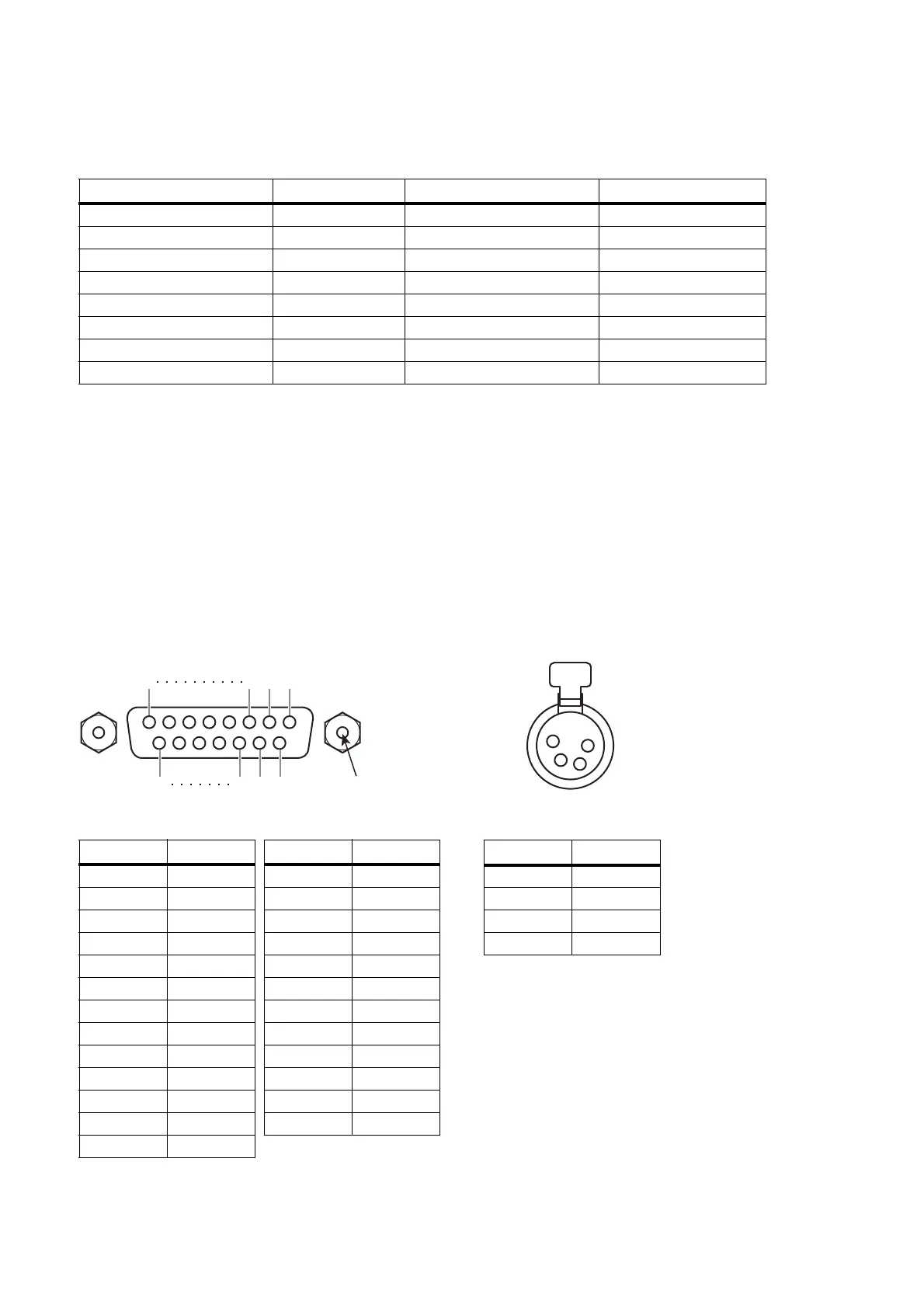
– – D-sub 25 pin (Female)
LAMP 1–3 – 0–12 V XLR-4-31 type
*6
*6. 3=GND, 4=+12 V; Up to 5 W is supported for lamp rating.
Pin No. Signal Pin No. Signal
1GPO1 14GPO2
2GPO3 15GPO4
3GPO5 16GPO6
4GPO7 17RLY_NC
5RLY_C 18RLY_NO
6GND 19GND
7 GND 20 OPTO-
8OPTO+ 21 +5V
9 +5V 22 GPI1
10 GPI2 23 GPI3
11 GPI4 24 GPI5
12 GPI6 25 GPI7
13 N.C.
141516
13
123
25
M2.6 x 0.45 mm pitch
Pin No. Signal
1N.C.
2N.C.
3GND
4+12V

 Loading...