
S
Samantha PierceAug 16, 2025
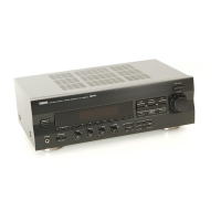
What to do if my Yamaha Stereo Receiver has no sound?
- Ccaleb06Aug 16, 2025
First, ensure that the output cords are correctly connected; if the problem continues, the cords may be defective. Also, be sure to press the input selector that corresponds to your input source.