EasyManua.ls Logo

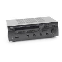
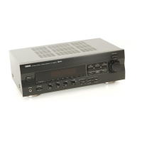
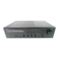
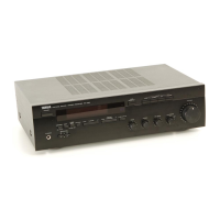
Yamaha RX-497 Service Manual

Yamaha RX-497
46 pages
To Next Page IconTo Next Page
Page #1 background imageLoading...
Page #1 background image
SERVICE MANUAL
This manual has been provided for the use of authorized YAMAHA Retailers and their service personnel.
It has been assumed that basic service procedures inherent to the industry, and more specifically YAMAHA Products, are already
known and understood by the users, and have therefore not been restated.
WARNING: Failure to follow appropriate service and safety procedures when servicing this product may result in personal
injury, destruction of expensive components, and failure of the product to perform as specified. For these reasons,
we advise all YAMAHA product owners that any service required should be performed by an authorized YAMAHA
Retailer or the appointed service representative.
IMPORTANT: The presentation or sale of this manual to any individual or firm does not constitute authorization, certification or
recognition of any applicable technical capabilities, or establish a principle-agent relationship of any form.
The data provided is believed to be accurate and applicable to the unit(s) indicated on the cover. The research, engineering, and service
departments of YAMAHA are continually striving to improve YAMAHA products. Modifications are, therefore, inevitable and
specifications are subject to change without notice or obligation to retrofit. Should any discrepancy appear to exist, please contact the
distributor's Service Division.
WARNING: Static discharges can destroy expensive components. Discharge any static electricity your body may have
accumulated by grounding yourself to the ground buss in the unit (heavy gauge black wires connect to this buss).
IMPORTANT: Turn the unit OFF during disassembly and part replacement. Recheck all work before you apply power to the unit.
IMPORTANT NOTICE
100977
SERVICE MANUAL
STEREO RECEIVER
AMP ADJUSTMENT . . . . . . . . . . . . . . . . . . . . . . . . . 16
IC DATA . . . . . . . . . . . . . . . . . . . . . . . . . . . . . . . . 17–18
DISPLAY DATA . . . . . . . . . . . . . . . . . . . . . . . . . . . . . 19
PIN CONNECTION DIAGRAM . . . . . . . . . . . . . . . . . 20
PRINTED CIRCUIT BOARD . . . . . . . . . . . . . . . . 21–27
BLOCK DIAGRAM . . . . . . . . . . . . . . . . . . . . . . . . . . . 28
SCHEMATIC DIAGRAM . . . . . . . . . . . . . . . . . . . 29–32
PARTS LIST . . . . . . . . . . . . . . . . . . . . . . . . . . . . . 33–43
REMOTE CONTROL RAX100/RAX101 . . . . . . . 44–45
CONTENTS
TO SERVICE PERSONNEL . . . . . . . . . . . . . . . . . . . . 2
IMPEDANCE SELECTOR . . . . . . . . . . . . . . . . . . . . . . 3
FRONT PANELS . . . . . . . . . . . . . . . . . . . . . . . . . . . . . 3
REAR PANELS . . . . . . . . . . . . . . . . . . . . . . . . . . . . 4–5
REMOTE CONTROL PANELS . . . . . . . . . . . . . . . . . . 5
SPECIFICATIONS . . . . . . . . . . . . . . . . . . . . . . . . . . 6–7
INTERNAL VIEW . . . . . . . . . . . . . . . . . . . . . . . . . . . . . 7
DISASSEMBLY PROCEDURES . . . . . . . . . . . . . . . . . 8
SELF DIAGNOSIS FUNCTION . . . . . . . . . . . . . . . 9–15
DPX-1200
RX-497
RX-497
© 2005 YAMAHA CORPORATION. All rights reseved.
This manual is copyrighted by YAMAHA and may not be copied or
redistributed either in print or electronically without permission.
’05.11
Other manuals for Yamaha RX-497

Questions and Answers:

Yamaha RX-497 Specifications

Audio Specifications IconAudio Specifications
minimum RMS output power75 W + 75 W
dynamic power105/125/150/178 W
maximum output power (Europe model only)105 W
IEC output power (Europe model only)84 W
power band width10 Hz to 50 kHz
damping factor150 or more
maximum output power (Asia and General models only)115 W
maximum input signal PHONO70 mV or more
maximum input signal CD, etc.2.2 V or more
frequency response CD, etc.0 ± 0.5 dB
frequency response CD, etc. PURE DIRECT ON0 ± 1.0 dB
RIAA equalization deviation PHONO± 0.5 dB
total harmonic distortion PHONO to OUT (REC)0.02% or less
total harmonic distortion CD, etc. to SPEAKERS0.02% or less
signal to noise ratio PHONO82 dB or more
signal to noise ratio CD, etc.108 dB or more
residual noise PURE DIRECT ON100 µV
gain tracking error2 dB or less
input sensitivity/input impedance PHONO3.0 mV/47 kΩ
input sensitivity/input impedance CD, etc.185 mV/47 kΩ
output level/output impedance OUT (REC)185 mV/1.2 kΩ or less
output level/output impedance SUB WOOFER OUTPUT4 V/1.2 kΩ or less
output level/output impedance ZONE 2 OUT185 mV/1.2 kΩ or less
headphone output/impedance0.47 V/390 Ω
channel separation (CD, etc.)65/50 dB or more
tone control characteristics BASS boost/cut±10 dB
tone control characteristics BASS turnover frequency350 Hz
tone control characteristics TREBLE boost/cut±10 dB
tone control characteristics TREBLE turnover frequency3.5 kHz
continuous loudness control attenuation–30 dB
Video Specifications IconVideo Specifications
video signal type (U.S.A., Canada and General models)NTSC
video signal type (Other models)PAL
signal to noise ratio50 dB or more
frequency response (MONITOR OUT)5 Hz to 10 MHz, –3 dB
FM Specifications IconFM Specifications
tuning range (U.S.A. and Canada models)87.5 to 107.9 MHz
tuning range (Asia and General models)87.5/87.50 to 107.9/108.00 MHz
tuning range (Other models)87.50 to 108.00 MHz
usable sensitivity (IHF)1.0 µV (11.2 dBf)
signal to noise ratio (Mono/Stereo)76 dB/70 dB
harmonic distortion (Mono/Stereo)0.2%/0.3%
stereo separation45 dB
frequency response20 Hz to 15 kHz, +0.5/–2 dB
AM Specifications IconAM Specifications
tuning range (U.S.A. and Canada models)530 to 1710 kHz
tuning range (Asia and General models)530/531 to 1710/1611 kHz
tuning range (Other models)531 to 1611 kHz
usable sensitivity300 µV/m
General Specifications IconGeneral Specifications
power supply (U.S.A. and Canada models)AC 120 V, 60 Hz
power supply (Asia model)AC 220/230-240 V, 50/60 Hz
power supply (General model)AC 110/120/220/230-240 V, 50/60 Hz
power supply (Australia model)AC 240 V, 50 Hz
power supply (Europe model)AC 230 V, 50 Hz
power consumption180 W
standby power consumption0.1 W
maximum power consumption (General model only)400 W
AC outlets (Australia model)1 (Total 100 W maximum)
AC outlets (General model)2 (Total 50 W maximum)
AC outlets (Other models)2 (Total 100 W maximum)
dimensions (W x H x D)435 x 151 x 308 mm (17-1/8” x 5-15/16” x 12-1/8”)
weight8.7 kg (19 lbs. 3 oz.)

Summary

Important Safety and Service Notice

Service Personnel Guidelines

Critical Components & Leakage Current Testing

Guidance on replacing critical components and performing leakage current measurements.

Impedance Selector Operation

Front Panel Layout and Controls

Rear Panel Connectivity

Remote Control Panels Overview

Technical Specifications

Audio Section Specifications

Output power, input sensitivity, frequency response, and distortion levels for the audio section.

FM/AM Section Specifications

Tuning ranges, sensitivity, selectivity, and separation for FM and AM reception.

General Unit Specifications

Details on power supply, consumption, dimensions, weight, and included accessories.

Internal Component Layout

Disassembly Procedures Guide

Top Cover and Front Panel Removal

Procedure for removing the top cover and front panel unit, including knob removal.

Sub Chassis Unit Extraction

Steps for removing the sub chassis unit, including connector disconnection.

Self-Diagnosis System Functions

Diagnostic Menu Overview

Details of the 8 main DIAG menu items: Display Check, Factory Preset, AD Data Check, etc.

Initiating Diagnostic Mode

Protection Cancel Mode for Diagnosis

Procedure to disable protection functions for diagnostic purposes, with caution notes.

Navigating Diagnostic Menus

DIAG Mode Operational Features

Lists functions like input selection, muting, and power control available during diagnosis.

Display Check Functionality

Factory Preset Initialization and Clearing

AD Data Check and Voltage Monitoring

DC/PS Protection Detection

Monitoring DC voltage and power supply values for protection triggers.

Panel Key Input (K0/K1) Analysis

Analysis of panel key input ports (KEY0/KEY1) AD values for proper operation.

Protection Setting Adjustments

Protection History Log

Soft Switch Configuration Options

Microprocessor Information Display

Amplifier Idling Current Adjustment

Microprocessor IC Data and Pinouts

Microprocessor IC Pin Details

FL Display Data and Segment Mapping

Display Pin Connection Diagram

Diagram showing pin numbers and their corresponding labels for the display driver IC.

Display Anode Connection Mapping

Mapping of display segment labels to specific pin numbers on the display driver IC.

Component Pin Connection Diagrams

Printed Circuit Board Layouts (Part 1)

Printed Circuit Board Layouts (Part 2)

Printed Circuit Board Layouts (Part 3)

Printed Circuit Board Layouts (Part 4)

Printed Circuit Board Layouts (Part 5)

Printed Circuit Board Layouts (Part 6)

Printed Circuit Board Layouts (Part 7)

System Block Diagram Overview

Functional Schematic Diagrams

Operation Schematic Diagrams

Main Unit Schematic Diagrams

XM Tuner Schematic Diagram

Electrical Parts List

Parts List Abbreviations

Explanation of abbreviations used for component types and materials in the parts list.

Function PCB Component Mapping

Function & Operation PCB Details

Operation & Main PCB Component Mapping

Main PCB Component Breakdown

XM PCB and Chip Resistor Listing

Carbon Resistor Part Number Guide

Exploded View of Unit Components

Mechanical Parts Identification

Mechanical Component Details

Included Accessories and Mechanical Parts

Remote Control Transmitter Schematic

RAX100 Remote Control Layout

Button layout diagram for the RAX100 remote control (U, C models).

RAX101 Remote Control Layout

Button layout diagram for the RAX101 remote control (R, A, G, E, L models).

Remote Control Data Code List

Related product manuals