RX-V671/HTR-6064
■ DISASSEMBLY PROCEDURES
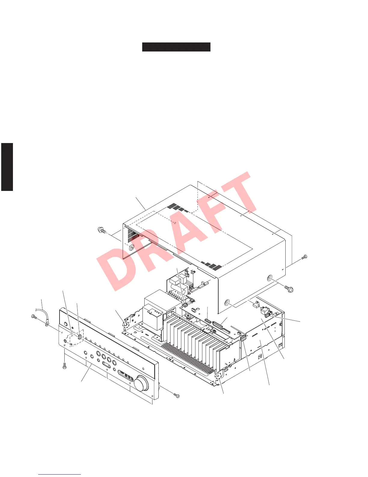
Fig. 1
RX-V671/HTR-6064
(Remove parts in the order as numbered.)
Disconnect the power cable from the AC outlet.
1. Removal of Top Cover
a. Remove 4 screws (
①
) and 5 screws (
②
). (Fig. 1)
b. Lift the rear of the top cover to remove it.
2. Removal of Front Panel Unit
a. Remove 7 screws (
③
), and remove W4401. (Fig. 1)
b. Remove CB10, CB81, CB458, CB472, CB902 and CB951 (Fig. 1)
c. Release 2 hooks, and remove the front panel unit. (Fig. 1)
Top cover
Front panel unit
CB472
W4401
OPERATION (3) P.C.B.
CB902
CB458
CB81
CB10
CB951
DIGITAL (1) P.C.B.
OPERATION (3) P.C.B.
Hook
Hook
①
①
②
③
③
③
18
RX-V671/HTR-6064/RX-A710
RX-V671/HTR-6064/
RX-A710