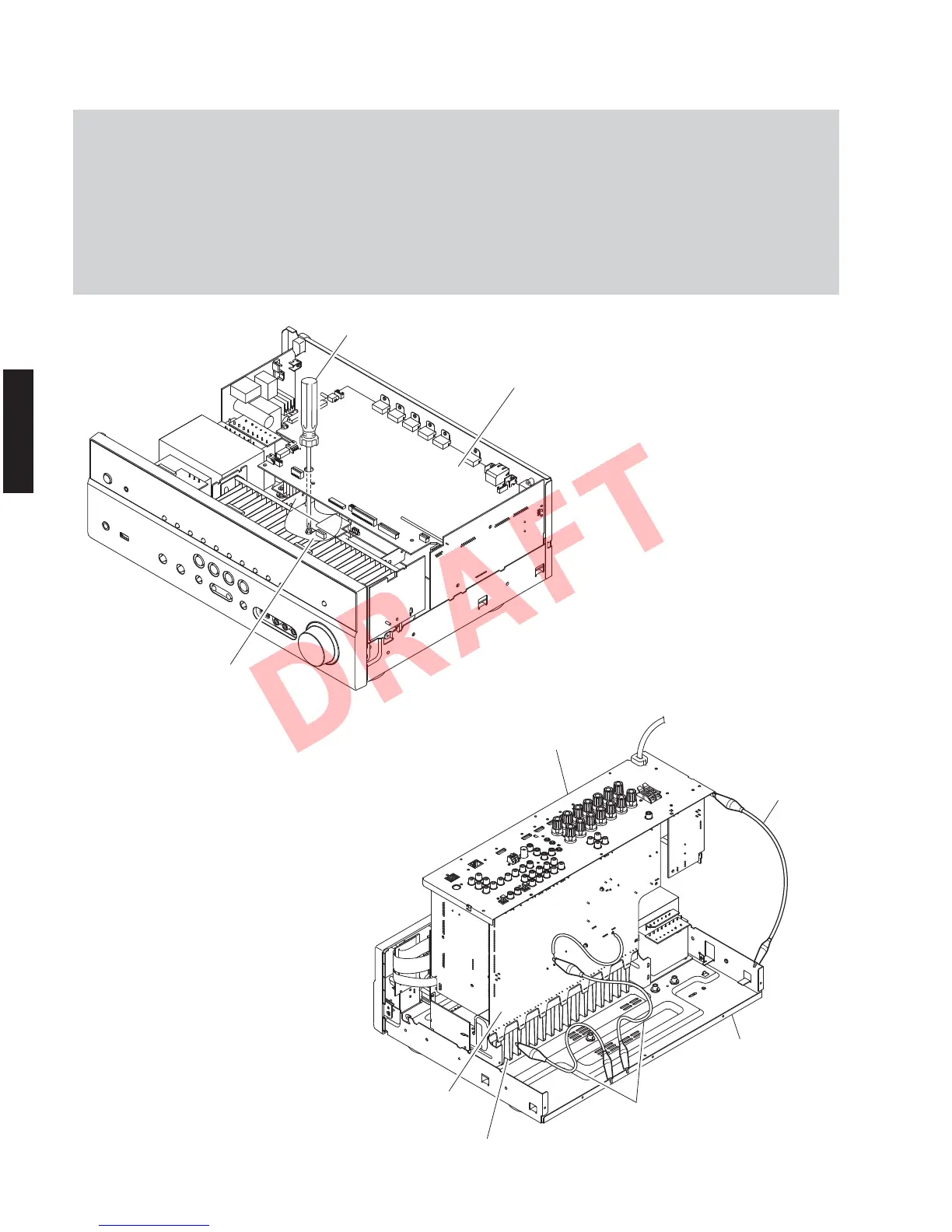
Rear panel
Heat sink
MAIN (1) P.C.B.
Chassis
Ground lead
Ground lead
When checking the P.C.B.s:
• Follow the procedure below to place the P.C.B.s (with rear panel) upright. (Fig. 5)
a. Remove the top cover. (Fig. 1)
b. Remove screw (
⑦
), 2 screws (
⑧
) and 4 screws (
⑨
). (Fig. 2)
c. Remove 3 screws (
⑩
). (Fig. 3)
• Connect the heatsink, rear panel and G101 on MAIN (1) P.C.B. to the chassis with a ground lead or the like. (Fig. 5)
• Reconnect all cables (connectors) that have been disconnected.
• When connecting the flexible flat cable, be careful with polarity.
Fig. 5
Fig. 4
MAIN (1) P.C.B.
DIGITAL (1) P.C.B.
Screw driver
⑦
20
RX-V671/HTR-6064/RX-A710
RX-V671/HTR-6064/
RX-A710
 Loading...