EasyManua.ls Logo

Yamaha RX-V771 Service Manual

Yamaha RX-V771
148 pages
To Next Page IconTo Next Page
Page #1 background imageLoading...
Page #1 background image
P.O.Box 1, Hamamatsu, Japan
101215
SERVICE MANUAL
IMPORTANT NOTICE
This manual has been provided for the use of authorized YAMAHA Retailers and their service personnel.
It has been assumed that basic service procedures inherent to the industry, and more speci cally YAMAHA Products, are already known
and understood by the users, and have therefore not been restated.
WARNING:
Failure to follow appropriate service and safety procedures when servicing this product may result in personal injury,
destruction of expensive components, and failure of the product to perform as speci ed. For these reasons, we advise
all YAMAHA product owners that any service required should be performed by an authorized YAMAHA Retailer or
the appointed service representative.
IMPORTANT:
The presentation or sale of this manual to any individual or rm does not constitute authorization, certi cation or
recognition of any applicable technical capabilities, or establish a principle-agent relationship of any form.
The data provided is believed to be accurate and applicable to the unit(s) indicated on the cover. The research, engineering, and service
departments of YAMAHA are continually striving to improve YAMAHA products. Modifications are, therefore, inevitable and
speci cations are subject to change without notice or obligation to retro t. Should any discrepancy appear to exist, please contact the
distributor's Service Division.
WARNING:
Static discharges can destroy expensive components. Discharge any static electricity your body may have
accumulated by grounding yourself to the ground buss in the unit (heavy gauge black wires connect to this buss).
IMPORTANT:
Turn the unit OFF during disassembly and part replacement. Recheck all work before you apply power to the unit.
CONTENTS
TO SERVICE PERSONNEL ............................................2
FRONT PANEL ...............................................................3
REAR PANELS ...........................................................3–5
REMOTE CONTROL PANELS .......................................6
SPECIFICATIONS /
参考仕様
................................... 7–12
INTERNAL VIEW ..........................................................13
SERVICE PRECAUTIONS /
サービス時の注意事項
..... 13
DISASSEMBLY PROCEDURES /
分解手順
........... 14–16
UPDATING FIRMWARE /
ファームウェアのアップデート
............................ 17–18
SELF-DIAGNOSTIC FUNCTION /
ダイアグ(自己診断機能)
..................................... 19–61
POWER AMPLIFIER ADJUSTMENT /
パワーアンプ調整
.......................................................62
DISPLAY DATA .......................................................63–64
IC DATA ...................................................................65–77
PIN CONNECTION DIAGRAMS .............................78–80
BLOCK DIAGRAMS ................................................81–85
PRINTED CIRCUIT BOARDS ............................... 86–105
SCHEMATIC DIAGRAMS ................................... 107–121
REPLACEMENT PARTS LIST ............................ 123–143
REMOTE CONTROL ........................................... 144–146
CONFIGURING THE SYSTEM SETTINGS ................. 147
システム設定を変更する
............................................. 148
AV RECEIVER
'11.06
Note:
When the DIGITAL P.C.B. or IC83 on DIGITAL P.C.B. is replaced, the network function of this unit will not operate
properly without additional setting.
In such a case, report the serial number of this unit to the following e-mail address.
Yamaha Corporation will reply providing the setting procedure to make the network function of this unit operate
properly.
注意:
DIGITALP.C.B. または DIGITALP.C.B. IC83 を交換すると本機のネットワーク機能が正常に動作しなくなり、正常
動作のための追加設定が必要になります。
そのような場合には本機のシリアルナンバーを下記の E メールアドレスへご連絡ください。
折り返し、ネットワーク機能が正常に動作するための追加設定方法をご連絡します。
E-mail: ycav-ysiss@gmx.yamaha.com
RX-V771
RX-V771
Copyright © 2011 All rights reserved.
This manual is copyrighted by YAMAHA and may not be copied or
redistributed either in print or electronically without permission.
Question and Answer IconNeed help?

Do you have a question about the Yamaha RX-V771 and is the answer not in the manual?

Yamaha RX-V771 Specifications

General IconGeneral
Receiver type-
RMS rated power1120 W
Output impedance4/8 Ω
Pre-out channels7.2
Pre-out connectivityYes
Audio output channels7.2 channels
Total Harmonic Distortion (THD)0.9 %
Dynamic power per channel (4 Ohm)210 W
Dynamic power per channel (8 Ohm)140 W
Power output per channel (1KHz@8 Ohm)130 W
Power output per channel (20-20KHz@8 Ohm)95 W
HDMI in6
Composite video in5
S-Video inputs quantity1
Component video (YPbPr/YCbCr) in2
S-Video outputs quantity0
Connectivity technologyWired
Speakers connectivity typeClamp terminals
Multichannel pre out connectivityRCA
Audio formats supportedFLAC, MP3, PCM, WAV, WMA
Ethernet LANNo
Supported radio bandsAM, FM
Internet radio services supportedNapster
Supported video modes1080p
Supported graphics resolutions1920 x 1080 (HD 1080)
Product colorBlack
Audio decodersDolby Digital Plus, Dolby Pro Logic IIx, Dolby TrueHD, DTS-HD
Volume controlRotary
Apple docking compatibilityNot supported
Power consumption (standby)0.1 W
HDMI ports quantity10
Compatible operating systemsWindows 7
Weight and Dimensions IconWeight and Dimensions
Depth368 mm
Width435 mm
Height171 mm
Weight11200 g

Summary

Important Notice and Service Precautions

Service and Safety Precautions

Advises servicing by authorized personnel and warns about static discharge and proper shutdown procedures.

Service Precautions

Safety Measures and High Voltage Warnings

General safety precautions, including high voltage warnings and capacitor discharge procedures.

Disassembly Procedures

Firmware Update Procedures

Firmware Update Requirements

Lists parts requiring firmware updates and the procedure for checking version/checksum.

Backup IC Initialization

Steps to initialize the backup IC (EEPROM) after firmware update.

Firmware Update Operation

Firmware Update Operation Procedures

Step-by-step guide for performing the firmware update using a USB device.

Self-Diagnostic Function Overview

Self-Diagnostic Function Activation

Starting Self-Diagnostic Function

Instructions on how to activate the self-diagnostic function.

Starting Self-Diagnostic Function in Protection Cancel Mode

Procedure to start self-diagnostic mode with protection functions disabled.

Self-Diagnostic Function Management

Canceling Self-Diagnostic Function

Steps to cancel the self-diagnostic function and restore default settings.

Protection Function Activation Scenarios

Protection Activated: Power Off and Excess Current

Explains protection history storage and activation due to excess current, with service notes.

Protection Function Activation Scenarios

Protection Activated: Abnormal DC Output and Voltage

Details protection activation due to abnormal DC output and power supply voltage, with safety notes.

Protection Function Activated: Heatsink Temperature

Protection Activated: Excessive Heatsink Temperature

Explains protection activation due to excessive heatsink temperature, potentially caused by poor ventilation.

Protection Function History

Information on how protection function history is stored and can be accessed.

Self-Diagnostic Function Menu Details

HDMI and Speaker Set Diagnostics

Manual Test Outputs

FL Display Check Procedures

Zone 2 and USB Diagnostics

iPod DOCK Check

Network Function Checks

IP Address and MAC Address Verification

Checks if an IP address can be obtained and if the MAC address is written.

Network Port External Test

Checks transmission/reception of the NETWORK port by shorting pins.

Line Noise and External Test

Checks network port transmission/reception and line noise.

Digital PCB Communication Checks

All Digital PCB Communication Checks

Displays the overall judgment result for sub-menus checking FLASH ROM, FPGA, and other bus connections.

I2C, BUS DIR, and BUS DSP1 Checks

Checks I2C, BUS DIR, and BUS DSP1 connections between microprocessors and other components.

EEPROM, LINK CHECK, and PHY TEST

Checks EEPROM reading, LAN cable connection, and PHY communication.

I2C EEPROM, BUS RAM, and SYNC SERIAL Checks

Checks I2C EEPROM, BUS RAM, and SYNC SERIAL connections.

Clock Generation and APL ID Check

Checks CLOCK IC reading and APPLE coprocessor device ID.

Analog Video Path Checks

Digital Video Path Checks

HDMI Loopback Test 1 Execution

Executes loopback test for all HDMI IN jacks by repeating a procedure.

HDMI Loopback Test 2 Execution

Executes loopback test for all HDMI IN jacks, including input source selection.

HDMI Repeat and Digital CVBS Signal Checks

Checks HDMI signal repeat and CVBS signal conversion/output.

Test Pattern Output Modes

System Monitor Functions

DC Output and Power Supply Voltage Monitoring

Detects power amplifier DC output and power supply voltages for protection checks.

System Monitor Functions

Panel Key A/D Value Monitoring

Detects panel key A/D values and checks for normal operation range.

Protection History and System Information

Protection Function History Display

Displays the history of the protection function, which can be erased by pressing STRAIGHT.

Factory Preset Options

Preset Initialization Control

Options to inhibit or reserve backup IC initialization, protecting user settings or allowing factory reset.

Firmware Version and Checksum Verification

Firmware Version and Checksum Verification

Power Amplifier Adjustment

Voltage Adjustment Procedure

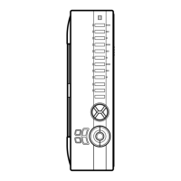
Procedure for adjusting and confirming voltage levels across power amplifier terminals after power-on and within specified times.

IC Data Specifications

Key Detection Data

Analog Multiplexer IC89 Specifications

I/O Expander IC308 Specifications

Network Microprocessor IC901 Specifications

Digital Section Block Diagram

Network and USB Section Block Diagram

Video Section Block Diagram

Power Supply Section Block Diagram

Digital Schematics (2/8)

Digital Schematics (3/8)

Digital Schematics (4/8)

Digital Schematics (5/8)

Digital Schematics (6/8)

Digital Schematics (7/8)

Digital Schematics (8/8)

Replacement Parts List

System Settings Configuration

Configuring System Settings

Related product manuals