Do you have a question about the Yamaha SR400 2014 and is the answer not in the manual?
Details about vehicle identification numbers and model labels.
Overview of the Fuel Injection (FI) system and its components.
Guidelines for preparation, parts replacement, and handling of specific components.
Information on handling quick fasteners and electrical systems.
List of specialized tools required for tune-up and assembly.
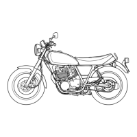
Overall dimensions, weight, and load capacity of the vehicle.
Detailed technical specifications for the engine, including bore, stroke, and oil capacity.
Technical details regarding the chassis, wheels, tires, and brakes.
Specifications for the electrical system, including voltage, ignition, and battery details.
Specifies torque values for various fasteners used in engine and chassis assembly.
Identifies lubrication points and the recommended lubricants for engine and chassis parts.
Visual representation of the engine oil lubrication flow and system components.
Diagrams illustrating the correct routing of wires, cables, and hoses on the vehicle.
General information and recommended checks and adjustments for vehicle maintenance.
Explains the importance of preventive maintenance for reliable operation and longevity.
Schedule of checks and maintenance for emission control system components.
Comprehensive chart of maintenance and lubrication tasks based on odometer reading.
Procedures for removing and installing seat covers, battery, and electrical components.
Steps for removing, disassembling, checking, and installing the front wheel assembly.
Procedures for removing, disassembling, checking, and installing the rear wheel and brake.
Detailed procedures for servicing the front brake system, including pads, caliper, and master cylinder.
Steps for disassembling, checking, and assembling the rear brake shoe plate.
Procedures for removing, checking, and installing the handlebar and related controls.
Instructions for removing, disassembling, checking, and assembling the front fork legs.
Procedures for removing, checking, and installing the steering head components.
Steps for removing, checking, and installing the rear shock absorber and swingarm.
Procedures for removing, checking, installing, and adjusting the drive chain.
Procedures for measuring engine compression pressure and checking spark plug.
Step-by-step guide for removing the engine from the vehicle.
Procedures for removing, checking, and installing the cylinder head and camshaft assembly.
Steps for removing, checking, and installing rocker arms and shafts.
Procedures for removing, checking, and installing valves, springs, and guides.
Steps for removing, checking, and installing the cylinder, piston, and rings.
Procedures for removing, checking, and installing clutch components.
Steps for removing, disassembling, and installing the kickstarter mechanism.
Procedures for removing, checking, and assembling the oil pump.
Steps for removing, checking, and installing the shift shaft and stopper lever.
Procedures for removing and installing the stator coil and AC magneto.
Steps for separating, disassembling, checking, and assembling the crankcase.
Procedures for removing, checking, and installing the crankshaft assembly.
Steps for removing, disassembling, checking, and assembling the transmission, shift forks, and drum.
Procedures for removing and installing the fuel tank, fuel pump case, and associated hoses.
Steps for removing, disassembling, checking, and adjusting the throttle body and sensors.
Procedures for checking and installing the air induction and air cut-off valve systems.
Circuit diagram and troubleshooting for the ignition system, including spark plug and coil.
Circuit diagram and troubleshooting for the charging system, including battery and stator.
Circuit diagram and troubleshooting for headlights, taillights, and indicators.
Circuit diagram and troubleshooting for turn signals, brake lights, and horn.
Circuit diagram, ECU self-diagnostics, and troubleshooting for the FI system.
Circuit diagram and troubleshooting for the fuel pump operation.
Identification and checking procedures for various electrical components like switches, fuses, and sensors.
General guidance for troubleshooting and referring to specific procedures in the manual.
Lists potential causes for engine starting problems related to engine, fuel, and electrical systems.
Lists potential causes for incorrect engine idling speed related to engine, fuel, and electrical systems.
Lists potential causes for poor engine performance at medium and high speeds.
Lists potential causes for difficulties in shifting gears or the shift pedal not moving.
Lists potential causes for a non-functional shift pedal.
Lists potential causes for the transmission jumping out of gear.
Lists potential causes for clutch slippage or dragging issues.
Lists potential causes for engine overheating related to engine, fuel, and chassis systems.
Lists potential causes for inadequate braking performance in disc and drum brakes.
Lists potential causes for issues with the front fork legs, such as oil leaks or damage.
Lists potential causes for unstable vehicle handling related to handlebar, steering, suspension, and frame.
Lists potential causes for failures in the lighting and signaling systems, including bulbs and wiring.
Provides a key for understanding the wire colors used in the wiring diagram.
| Engine Type | Air-cooled, 4-stroke, SOHC, 2-valve |
|---|---|
| Displacement | 399cc |
| Bore x Stroke | 87.0 x 62.7 mm |
| Compression Ratio | 8.5:1 |
| Fuel System | Fuel Injection |
| Transmission | 5-speed |
| Final Drive | Chain |
| Front Suspension | Telescopic fork |
| Rear Suspension | Swingarm |
| Front Brake | Single disc |
| Rear Brake | Drum |
| Front Tire | 90/100-18M/C 54S |
| Rear Tire | 110/90-18M/C 61S |
| Ignition System | TCI |
| Fuel Tank Capacity | 12 liters |
| Curb Weight | 174 kg |
| Wheelbase | 1, 410 mm |
| Length | 2, 085 mm |
| Width | 750 mm |