Do you have a question about the Yamaha T5n and is the answer not in the manual?
Covers safety, chemical content, and general warnings.
Specific instructions for connecting the plug and cord in the UK.
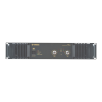
Detailed technical specifications for the T5n model.
Detailed technical specifications for the T4n model.
Detailed technical specifications for the T3n model.
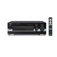
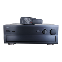
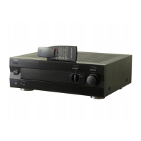
Identification of controls and indicators on the front panel.
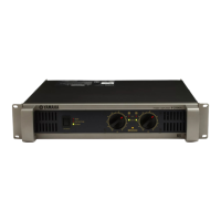
Identification of connectors and terminals on the rear panel.
Step-by-step guide to remove the top cover.
Procedure to remove the PA unit from the left side.
Procedure to remove the PA unit from the right side.
Step-by-step guide to remove the rear assembly.
Procedure to remove INT and INSWT circuit boards.
Step-by-step guide to remove the front assembly.
Procedure to remove the DC fan assembly.
Procedure to remove PSWT, FPT, and ATTT circuit boards.
Procedure to remove PST and CPUT circuit boards.
Specifies environment, power source, and instruments for testing.
Checks the status of LEDs and fan rotation.
Covers fan, LED, muting, idling current, DC voltage, efficiency, gain, and frequency response.
Procedures for checking distortion and maximum output levels.
Tests for channel separation, noise, stability, and protection circuits.
Checks limiter, compressor, and signal LED functionality.
Steps for preparing and performing inspections in BRIDGE mode.
Connection and software setup for data port testing.
Performing initial, remote, and model ID checks.
Details of automated tests (10-40) for performance verification.
Details of automated tests (50-70) for performance verification.
Details of automated tests (80-90) for performance verification.
Interpreting test results and identifying failures.
Identifies circuit boards covered by this repair guide.
Procedures for verifying electrical performance parameters.
Safety steps for discharging capacitors before handling boards.
General instructions for troubleshooting and component replacement.
Flowchart for checking AC voltage and signal waveforms.
List of parts for the complete amplifier assembly.
List of parts specific to the rear assembly.
List of parts specific to the front assembly.
List of parts for the PA unit.
List of individual electrical components used in the amplifier.
Visual representations of integrated circuits and diodes.
Diagram illustrating the internal wiring of the entire unit.
High-level functional overview of the amplifier's internal blocks.
Collection of main circuit diagrams for different sections.
| Type | Power Amplifier |
|---|---|
| Channels | 2 |
| Frequency Response | 20Hz - 20kHz |
| Input Impedance | 20 kOhms (Balanced), 10 kOhms (Unbalanced) |
| THD+N | 0.1% |
| Signal-to-Noise Ratio | 100dB |
| Damping Factor | ≥200 |
| Connectors (Input) | XLR, TRS |
| Connectors (Output) | Binding Posts, Speakon |
| Dimensions | 480 x 456 mm |
| Inputs | 2 |
| Outputs | 2 |