UD-Stomp
11
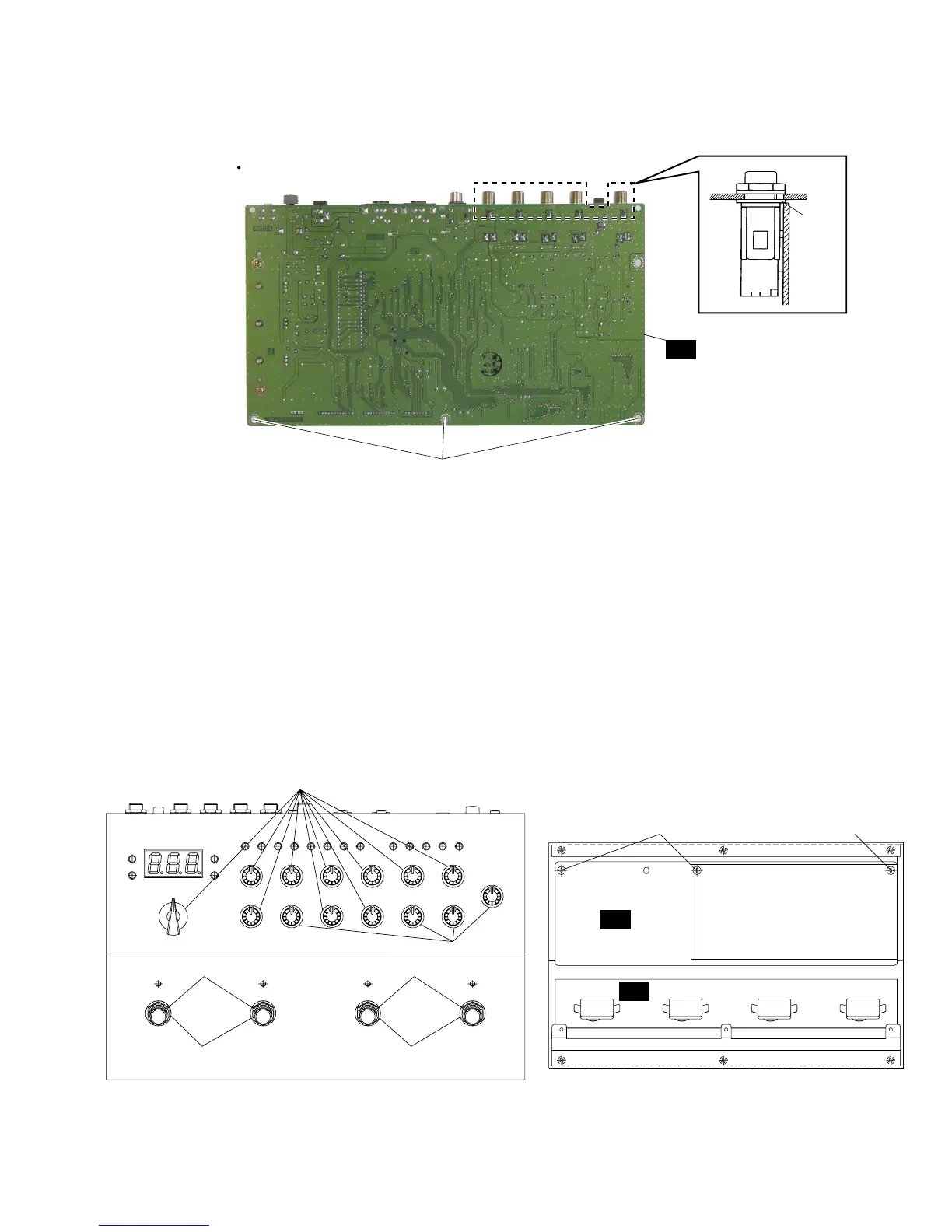
Fig.2
Fig.3
[T80]:Flat Washer 12x17 0.5 MFNI33 (V7407400)
[T110]:Bind Head Tapping Screw-B 3.0x8 MFZN2BL (EP600190)
[T70]:Washer 9.0 MFZN2Y (ET800150)
[T110]:Bind Head Tapping Screw-B 3.0x8 MFZN2BL (EP600190)
3. PN1/2 Circuit Boards
(Manhour requirement: 13 min.)
3-1. Remove the bottom case. (See Procedure 1.)
3-2. Remove the DM circuit board. (See Procedure 2.)
3-3. Remove the controls, knobs and the fourteen (14)
hexagonal nuts A from the front panel, the three (3)
screws marked [T110] and the shield film from the
PN1/2 circuit board. The PN1/2 circuit board can then
be removed. (Fig. 3)
4. PN 2/2 Circuit Board (Manhour requirement: 10 min.)
4-1. Remove the bottom case. (See Procedure 1.)
4-2. Remove the DM circuit boards. (See Procedure 2.)
4-3. Remove the four (4) hexagonal nuts B and the four (4)
flat washers marked [T80] from foot switches. The PN
2/2 circuit board can then be removed. (Fig. 3)
Hexagonal Nut A
Hexagonal Nut A
Hexagonal Nut B
1/2
[T110]
[T80] [T80]
[T110]
shield sheet
PN
2/2PN
Hexagonal Nut B
[T110B]
DM
Topcover
[T70]
 Loading...