27
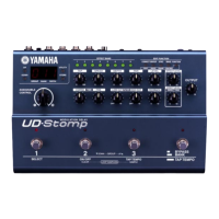
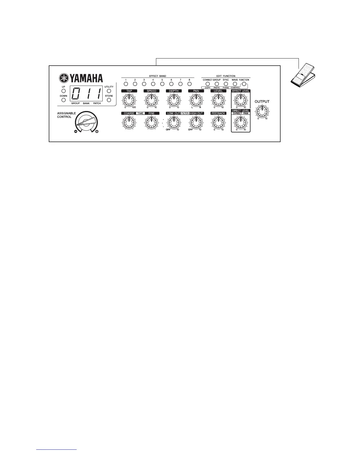
UD-Stomp
!3
FC7 Foot Controller
p
q
uio!0!1
!2
wert
y
Fig.2
3: Battery check
(1) Using the UP and DOWN switches, select “3”.
(This step can be skipped if “3” has already been
selected.)
(2) Press the STORE switch.
• If the check result is OK, all lights light up, go off and
the program proceed to the next step.
• If the check result is unsatisfactory, “E” appears at
the left end of the LED.
4: MIDI Check
(1) Using the UP and DOWN switches, select “4”.
(This step can be skipped if “4” is already selected.)
(2) Press the STORE switch.
• If the check result is OK, all LED segments light up
and go out. The checking function will proceed to the
next step.
• In case of an error, “E” appears at the left end of
the LED. “0” at the right end indicates transmission
and “1” indicates reception.
5: SRAM Check
(1) Using the UP and DOWN switches, select “5”.
(This step can be skipped if “5” is already selected.)
(2) Press the STORE switch.
• If the check result is OK, all LED segments light up
and go out. The checking function will proceed to the
next step.
• In case of an error, “E” appears at the left end of the LED.
“0” at the right end indicates IC2 and “1” indicates IC3.
6: DSP Electric Characteristic
(1) Using the UP and DOWN switches, select “6”.
(This step can be skipped if “6” is already selected.)
(2) Press the STORE switch.
• An input signal will be output when the STORE
switch is pressed. “1” appears at the right end of
the LED. (Table.1)
• The sine waveform can be checked in all of the analog
circuit, A/D, DSP-6 and D/A where the signal has
passed.
• Initial setting: OUTPUT VR
••• MAX
: HIGH/LOW SW
••• OFF (LOW)
: The input impedance of the measuring
in strum ent should be 1MΩ or more.
 Loading...