- 27 -
–+
ELEC
ELECTRICAL
CHECKING OF SWITCHES
NOTE:
This section is written based on a general model.
Check the switches for the continuity between
the terminal to determine correct connection.
Read the following for switch inspection.
SWITCH CONNECTION AS SHOWN IN
MANUAL
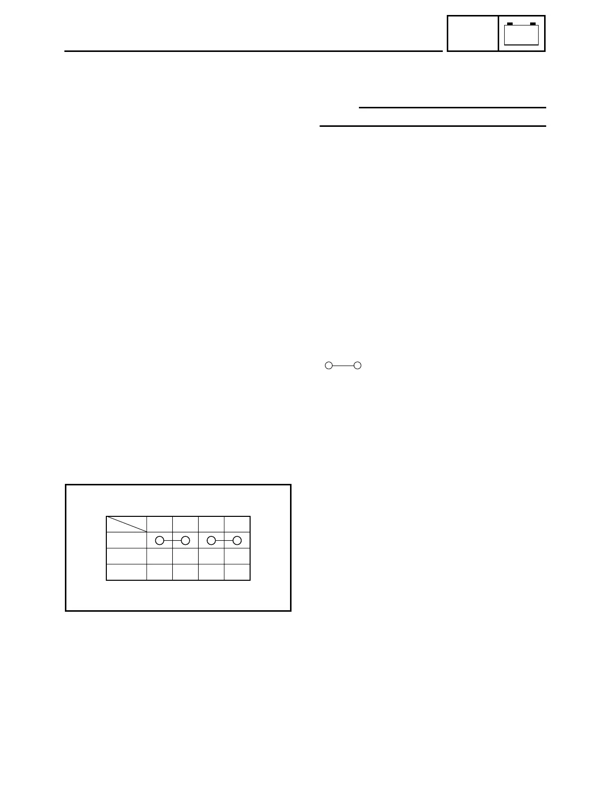
The manual contains a connection chart as
shown left showing the terminal connections of
the switches (e.g., main switch, handlebar
switch, bracket switch, lighting switch etc.).
The extreme left column indicates the switch
positions and the top line indicates the colors
of leads of connected with the terminals in the
switch component.
“ ” indicates the terminals between
which there is a continuity of electricity; i.e., a
closed circuit at the respective switch posi-
tions.
In this chart:
“R and Br” and “B/W and B” are continuous
with the “ON” switch position.
ON
R Br B/W B
OFF
LOCK
CHECKING SWITCH FOR TERMINAL
CONNECTION
Before checking the switch, refer to the con-
nection chart as shown above and check for
the correct terminal connection (closed circuit)
by the color combination.
To explain how to check the switch, the main
switch taken for example in the following.
CHECKING OF SWITCHES



 To Next Page