Do you have a question about the Yamaha YBR250 2007 and is the answer not in the manual?
Details on identifying the vehicle's VIN and model label for service.
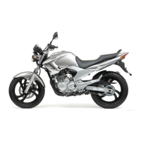
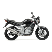
Overview of the motorcycle's main features, including the FI system.
Crucial guidelines for maintenance, parts, and safety before starting work.
Procedure for inspecting electrical connections for stains, rust, and moisture.
List of specialized tools required for tune-up and assembly procedures.
Basic dimensional and weight data for the YBR250 model.
Detailed technical data for the engine, including dimensions, fuel, and oil.
Specifications related to the frame, wheels, tires, brakes, and suspension systems.
Technical data for the ignition, starting, charging, lighting, and signaling systems.
Specifies tightening torques for standard fasteners and components.
Identifies lubrication points and recommended lubricant types for engine and chassis.
Illustrates the correct routing for various wires, cables, and hoses on the motorcycle.
Schedule of routine maintenance tasks based on odometer reading and annual checks.
Procedure for removing and installing side covers and related components.
Steps for removing, checking, and installing the fuel tank and pump.
Covers valve clearance, idle speed, throttle play, compression, and fluid levels.
Procedures for checking brakes, tires, steering head, forks, and suspension.
Guidance on checking battery, fuses, bulbs, and basic system operations.
Procedures for removing, checking, and installing the front wheel and brake disc.
Service procedures for the rear wheel, brake disc, and sprocket assembly.
Detailed information on brake pads, master cylinder, and calipers.
Instructions for removing, disassembling, checking, assembling, and installing front fork legs.
Procedures for removing, checking, and installing the handlebar.
Steps for removing, checking, and installing the steering head components.
Guidelines for handling, disposing, removing, checking, and installing the rear shock absorber.
Maintenance and inspection of the swingarm and drive chain.
Steps for removing the engine, including exhaust, leads, and ignition coil.
Procedures for removing, checking, and installing the cylinder head and related parts.
Service information for removing, checking, and installing rocker arms and camshaft.
Steps for removing, checking, and installing valves, springs, and guides.
Procedures for removing, checking, and installing the cylinder, piston, and rings.
Details on clutch cover, pull lever shaft, and clutch assembly service.
Information on oil pump and balancer gear removal, checking, and assembly.
Procedures for checking and assembling the oil cooler system.
Steps for disassembling, checking, and installing the shift shaft and stopper lever.
Service procedures for the starter clutch and AC magneto.
Instructions for disassembling, checking, and assembling the crankshaft and crankcases.
Procedures for removing, checking, and installing the transmission components.
Service information for the main axle and drive axle assemblies.
Schematic diagram of the motorcycle's electrical system for fuel injection.
Explanation of the ECU's self-diagnostic capabilities and fault code indications.
Reference table detailing fault codes, symptoms, fail-safe actions, and vehicle operability.
General procedures for diagnosing and resolving fuel injection system issues.
Steps for accessing and using the F.I. diagnostic tool in normal and diagnostic modes.
Specific troubleshooting steps for each fault code number displayed by the FI diagnostic tool.
Procedures for removing, checking, and installing the throttle body and related components.
Information on the air induction system, including diagrams and checks.
Diagram showing the location of various electrical system components on the motorcycle.
Procedure for testing switch continuity using a pocket tester.
Guidance on checking each switch for damage, wear, connections, and continuity.
Instructions for checking bulbs and sockets for damage, wear, and continuity.
Details on the ignition system, including circuit diagrams and troubleshooting.
Information on the electric starting system, circuit diagrams, and troubleshooting.
Procedures for removing, checking, and assembling the starter motor.
Details on the charging system, circuit diagrams, and troubleshooting.
Information on the lighting system, including circuit diagrams and troubleshooting.
Details on the signaling system, circuit diagrams, and troubleshooting.
Troubleshooting guide for engine and fuel system issues that prevent starting.
Diagnosing and resolving problems related to unstable or incorrect engine idling speed.
Troubleshooting steps for performance issues at medium and high speeds.
Diagnosing and resolving problems with gear shifting difficulty or jumps out of gear.
Troubleshooting for clutch slip, drag, and other related issues.
Identifying causes and solutions for engine and brake overheating.
Troubleshooting steps for issues like worn pads, fluid leaks, or brake drag.
Diagnosing and resolving problems related to oil leaks or unstable handling from front forks.
Troubleshooting causes of unstable handling related to tires, wheels, frame, and suspension.
Diagnosing and fixing issues with headlights, taillights, turn signals, and horn.
Reference for electrical circuit diagrams and wire color codes.
| Displacement | 249 cc |
|---|---|
| Bore x Stroke | 74.0 mm x 58.0 mm |
| Compression Ratio | 9.8:1 |
| Fuel System | Carburetor |
| Ignition | TCI |
| Transmission | 5-speed |
| Final Drive | Chain |
| Front Suspension | Telescopic fork |
| Rear Suspension | Swingarm (monocross) |
| Front Brake | Single disc |
| Rear Brake | Drum |
| Overall Width | 745 mm |
| Overall Height | 1, 065 mm |
| Seat Height | 780 mm |
| Wheelbase | 1, 360 mm |
| Ground Clearance | 175 mm |
| Fuel Capacity | 19.2 liters |
| Dry Weight | 138 kg |
| Engine Type | Air-cooled, 4-stroke, SOHC, 2-valve, single cylinder |
| Maximum Torque | 20.0Nm @ 6, 500rpm |
| Rear Tire | 130/70-17M/C 62H |