EasyManua.ls Logo

Yamatake DMC10 Series User Manual

Default Icon
156 pages
To Next Page IconTo Next Page
Page #1 background imageLoading...
Page #1 background image
1
Yamatake Corporation
Digital Controller SIO
Driver
1 System Configuration.......................................................................................................3
2 Selection of External Device............................................................................................9
3 Example of Communication Setting...............................................................................10
4 Setup Items....................................................................................................................74
5 Cable Diagram ...............................................................................................................79
6 Supported Devices.......................................................................................................138
7 Device Code and Address Code..................................................................................152
8 Error Messages............................................................................................................156

Table of Contents

Question and Answer IconNeed help?

Do you have a question about the Yamatake DMC10 Series and is the answer not in the manual?
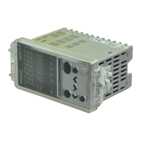
Yamatake DMC10 Series Specifications

General IconGeneral
Accuracy±0.3% of span ±1 digit
Control MethodPID control
Input TypeThermocouple, RTD, DC voltage
Output TypeRelay, voltage pulse, current
Control OutputRelay contact, Voltage pulse, DC current
Alarm OutputRelay contact
Power Supply100 to 240 VAC, 50/60 Hz or 24 VAC/VDC
DisplayLED display
Dimensions96x96mm
TypeDigital Controller

Summary

System Configuration

Selection of External Device

Example of Communication Setting

3.1 Setting Example 1

Details GP-Pro EX and external device communication settings.

3.10 Setting Example 10

Details GP-Pro EX and external device communication settings.

3.20 Setting Example 20

Details GP-Pro EX and external device communication settings.

3.30 Setting Example 30

Details GP-Pro EX and external device communication settings.

Setup Items

4.1 Setup Items in GP-Pro EX

Describes communication parameters configurable in GP-Pro EX.

4.2 Settings in Off-Line Mode

Explains configuring communication settings in off-line mode.

Cable Diagram

Cable Diagram 1

Shows cable connections for GP3000, GP4105 with specific ports.

Cable Diagram 2

Details cable configurations for GP3000 series, IPC, and GP-4106.

Cable Diagram 3

Illustrates cable diagrams for GP3000 series, IPC, GP-4106, and GP-4107.

Cable Diagram 4

Provides cabling details for GP3000 series, IPC, GP-4106, and GP-4107.

Supported Devices

6.1 SDC10

Specifies device and address ranges for SDC10.

6.2 SDC15/SDC25/SDC26/SDC35/SDC36

Specifies device and address ranges for SDC15/25/26/35/36.

6.5 SDC40A

Specifies device and address ranges for SDC40A.

6.10 DMC50

Specifies device and address ranges for DMC50.

6.13 DCP552

Specifies device and address ranges for DCP552.

Device Code and Address Code

7.1 SDC10

Lists device code and address for SDC10.

7.3 SDC20/SDC21

Lists device code and address for SDC20/21.

7.5 SDC40A

Lists device code and address for SDC40A.

7.10 DMC50

Lists device codes and addresses for DMC50.

7.14 CMC10B

Lists device code and address for CMC10B.

Error Messages

Related product manuals