C
Connie MartinAug 1, 2025
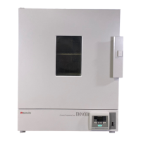
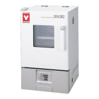
Why temperature in chamber does not rise in my Yamato DKN302C?
- MmatthewsallisonAug 1, 2025
If the temperature in the chamber of your Yamato Convection Oven does not rise, check the following: * Ensure the temperature setting is higher than the current chamber temperature. * Verify that the power supply voltage hasn't dropped. * Confirm the external temperature is within the operable range (5°C~35°C). * Make sure the chamber isn't overloaded with too many samples.