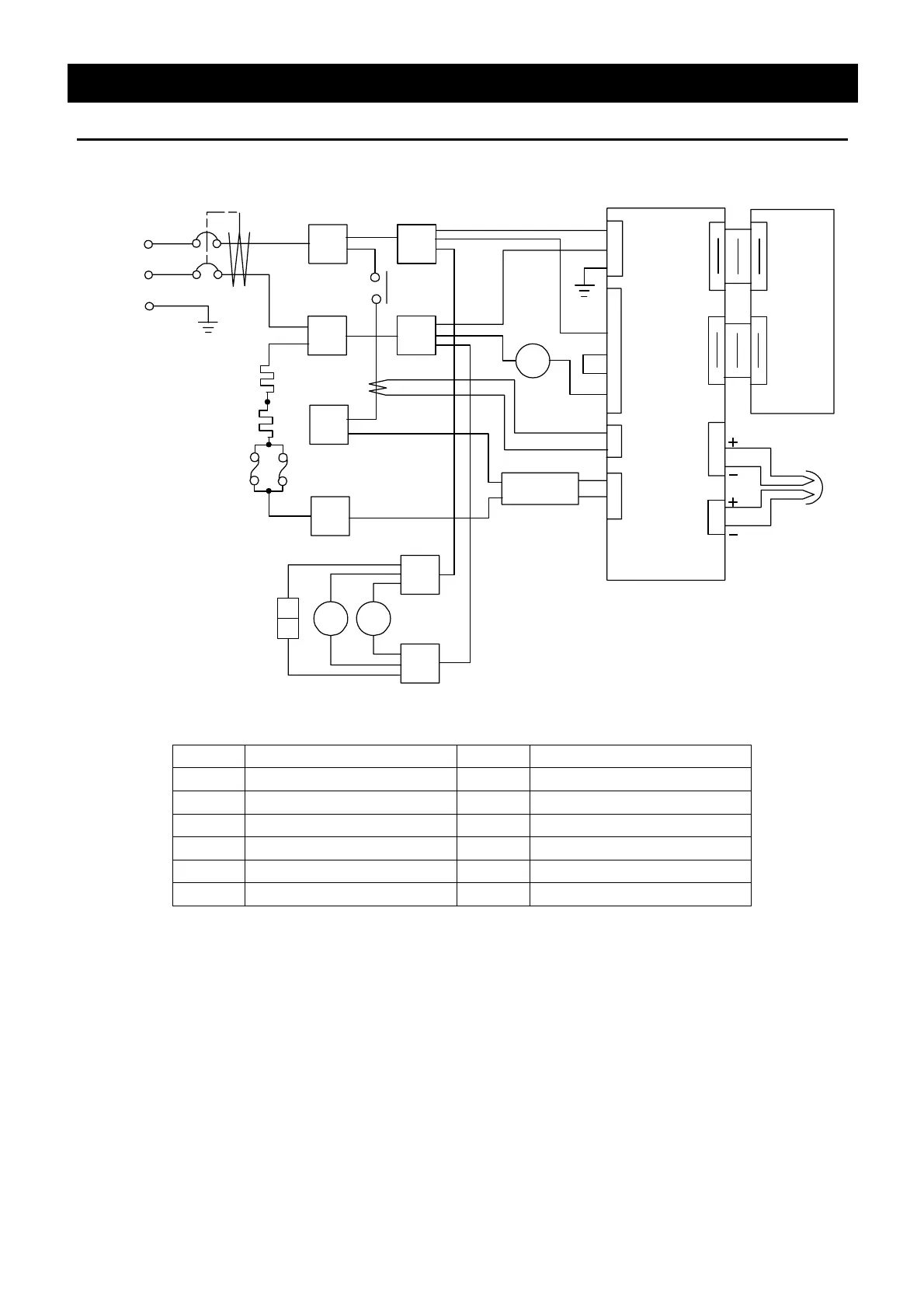
42
Wiring Diagram
FO610/710/810
FM1
ELB
1
2
CN
H1
H2
AC200V
F
FM2
PIO
CN1
1
18
18
11
1
1
1
1
2
3
4
3
2
2
3
6
X1
X1
CN8
SSR
1
2
TB1
TIC
CN5
CN1
CN2
CN4
CT
P2
1
2
P1
CN2
1
18
18
1
CN9
3
2
1
2
2
3
4
5
3
TB2
2
1
3
4
TH
4
・
・
・
・
・
・
・
・
Symbol Part name Symbol Part name
ELB Earth leakage breaker F Thermal fuse
P1,P2 Terminal block FM Fan motor
CT Current transformer TIC Control board
H1,H2 Heater PIO Display circuit board
TH W sensor CN Connector for exhaust system
X1 Main relay SSR Solid state relay