MULTI
CYLINDER
ENGINES
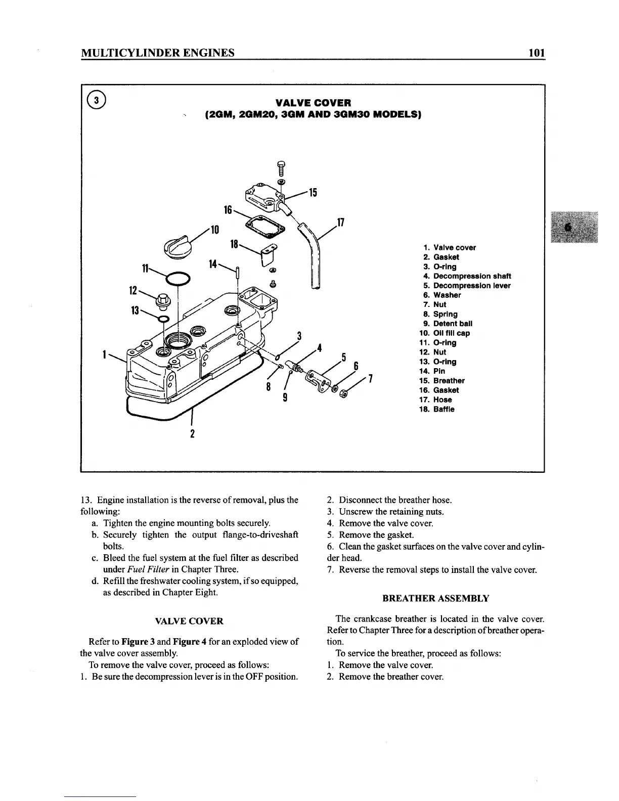
VALVE
COVER
(2GM,
2GM20,
3GM
AND
3GM30
MODELS)
101
1. Valve cover
2. Gasket
3. O-ring
4. Decompression shaft
5. Decompression lever
6. Washer
7. Nut
8. Spring
9. Detent ball
10.
011
fill cap
11. O-ring
12. Nut
13. O-ring
14. Pin
15. Breather
16. Gasket
17. Hose
18. Baffle
2
13. Engine installation is the reverse
of
removal, plus the
following:
a. Tighten the engine mounting bolts securely.
b. Securely tighten the output flange-to-driveshaft
bolts.
c. Bleed the fuel system at the fuel filter as described
under Fuel Filter in Chapter Three.
d. Refill the freshwater cooling system,
if
so equipped,
as described in Chapter Eight.
VALVE
COVER
Refer to Figure 3 and Figure 4 for an exploded view
of
the valve cover assembly.
To remove the valve cover, proceed as follows:
1. Be sure the decompression lever is in the OFF position.
2. Disconnect the breather hose.
3. Unscrew the retaining nuts.
4. Remove the valve cover.
5. Remove the gasket.
6. Clean the gasket surfaces on the valve cover and cylin-
der head.
7. Reverse the removal steps to install the valve cover.
BREATHER ASSEMBLY
The crankcase breather is located in the valve cover.
Refer to ChapterThree for a description
of
breatheropera-
tion.
To service the breather, proceed as follows:
1. Remove the valve cover.
2. Remove the breather cover.